
Amplifier Circuit
Index 40
An Amplified Zener
Published:2012/10/25 21:15:00 Author:muriel | Keyword: An Amplified Zener

View full Circuit Diagram | Comments | Reading(1222)
Complete Surround System
Published:2012/10/25 2:42:00 Author:muriel | Keyword: Complete, Surround System

A complete surround system would consist of a power supply, the decoder matrix, optionally the stereo width controller, and the delay unit. Figure 3 shows my suggested method of interconnecting the units, which can all be housed in a single case. For the more adventurous, you can add a pair of Linkwitz-Riley crossovers for bi-amping (shown in the dotted box) for the front left and right speakers.
This keeps everything together, and only the switches needs to be accessible in normal use. All level controls should be set to the desired volume, and not fiddled with once you have it the way you want. If these are accessible, everyone will want to fiddle, and you will then have to try to set it back to where you want - until someone else comes and fiddles again. (View)
View full Circuit Diagram | Comments | Reading(2258)
Audio levels meter
Published:2012/10/25 2:29:00 Author:muriel | Keyword: Audio levels meter

Audio levels can be monitored using a small panel meter with this circuit built from discrete components. (View)
View full Circuit Diagram | Comments | Reading(855)
Audio Graphic Equaliser
Published:2012/10/25 2:28:00 Author:muriel | Keyword: Audio Graphic Equaliser

Audio graphic equalizers are very common as commercial products (for Hi-fi, car audio and stage use) but circuits for them are very rarely published. I didn't design this one but it's really very simple. The details shown are for a 7 band but the principle can be extended to almost any number of bands - if you can find accurate enough components. (View)
View full Circuit Diagram | Comments | Reading(860)
300W Subwoofer Power Amplifier
Published:2012/10/25 2:24:00 Author:muriel | Keyword: 300W , Subwoofer , Power Amplifier

Please note that the specification for this amp has been upgraded, and it is now recommended for continuous high power into 4 Ohms, but You will need to go to extremes with the heatsink (fan cooling is highly recommended). It was originally intended for light intermittent duty, suitable for an equalised subwoofer system (for example using the ELF principle - see the Project Page for the info on this circuit). Where continuous high power is required, another 4 output transistors are recommended, wired in the same way as Q9, Q10, Q11 and Q12, and using 0.33 ohm emitter resistors.
Continuous power into 8 ohms is typically over 150W (250W for ±70V supplies), and it can be used without additional transistors at full power into an 8 ohm load all day, every day. The additional transistors are only needed if you want to do the same thing into 4 ohms at maximum supply voltage! Do not even think about using supplies over ±70V, and don't bother asking me if it is ok - it isn't!
The circuit is shown in Figure 1, and it is a reasonably conventional design. Connections are provided for the Internal SIM (published elsewhere on the Project Pages), and filtering is provided for RF protection (R1, C2). The input is via a 4.7uF bipolar cap, as this provides lots of capacitance in a small size. Because of the impedance, little or no degradation of sound will be apparent. A polyester cap may be used if you prefer - 1uF with the nominal 22k input impedance will give a -3dB frequency of 7.2Hz, which is quite low enough for any sub. (View)
View full Circuit Diagram | Comments | Reading(2789)
A 2 Watt audio amplifier
Published:2012/10/25 2:23:00 Author:muriel | Keyword: 2 Watt, audio amplifier

A 2 Watt audio amplifier made from discrete components. (View)
View full Circuit Diagram | Comments | Reading(1184)
High Current MOSFET Toggle Switch with Debounced Push Button.
Published:2012/10/22 22:15:00 Author:muriel | Keyword: High Current MOSFET , Toggle Switch , Debounced Push Button

This circuit was adapted from the Toggle Switch Debounced Pushbutton by John Lundgren. It is useful where the load needs to be switched on from one location and switched off from another. Any number of momentary (N/O) switches or push buttons can be connected in parallel.
The combination (10K, 10uF and diode) on the left side of the schematic insures the circuit powers up with the load turned off and the NPN transistor conducting. These components can be omitted if the initial power-on condition is not an issue.
When a switch is closed, the 1uF cap voltage is connected to the junction of the 220 ohm and 33K resistors causing the circuit to change state. When the switch is opened, the cap charges or discharges to the new level through the 1M resistor, and the circuit is ready to toggle again in about 1 second. It takes a little time for the cap to move to the new level, either +V or ground.
The (0.1uF) capacitor at the transistor base was added to supress noise that might cause false triggering if the switches are located far away from the circuit. The circuit was tested using a 12 volt, 25 watt automotive lamp, and IRFZ44. Other MOSFETs can probably be used.
(View)
View full Circuit Diagram | Comments | Reading(1508)
Very High Gain Crystal Earphone Amplifier
Published:2012/10/22 22:06:00 Author:muriel | Keyword: Very High Gain , Crystal Earphone, Amplifier

This simple, one-transistor amplifier provides a voltage gain over 1000 (60 dB) for driving a high impedance ceramic (crystal) earphone. The high gain is achieved by replacing the traditional collector resistor with an unusual constant-current diode that supplies 1/2 mA yet exhibits a very high resistance to the audio. This amplifier will give excellent battery life, drawing only 500 uA. (View)
View full Circuit Diagram | Comments | Reading(1471)
Crystal Radio RF Amplifiers
Published:2012/10/22 22:05:00 Author:muriel | Keyword: Crystal Radio, RF Amplifiers

One of the best places to add a transistor to a simple crystal radio is at the front end in the form of an RF amplifier. The circuit below is a simple but effective amplifier which will give surprising performance improvement. This amplifier can exhibit negative resistance for low settings of the 500 ohm pot which results in extra gain or even oscillation. So, the circuit can actually be considered to be a regenerative receiver with an external detector. The sensitivity is so high that no cold water pipe ground is needed and the antenna is short. (View)
View full Circuit Diagram | Comments | Reading(2167)
Crystal Radio Audio Amplifiers
Published:2012/10/22 22:05:00 Author:muriel | Keyword: Crystal Radio, Audio Amplifiers

Here is a simple audio amplifier using a TL431 shunt regulator. The amplifier will provide room-filling volume from an ordinary crystal radio outfitted with a long-wire antenna and good ground. The circuitry is similar in complexity to a simple one-transistor radio but the performance is far superior. The TL431 is available in a TO-92 package and it looks like an ordinary transistor so your hobbyist friends will be impressed by the volume you are getting with only one transistor! The amplifier may be used for other projects, too. Higher impedance headphones and speakers may also be used. An earphone from an old telephone will give ear-splitting volume and great sensitivity! The 68 ohm resistor may be increased to several hundred ohms when using high impedance earphones to save battery power. (View)
View full Circuit Diagram | Comments | Reading(1260)
One Transistor Amplifier/Detector
Published:2012/10/22 22:04:00 Author:muriel | Keyword: One Transistor , Amplifier, Detector

An amplifier may be added to boost the audio level as shown below. The current consumption of this amplifier is quite low and a power switch is not included. Disconnect the battery when the receiver is stored for long periods. (View)
View full Circuit Diagram | Comments | Reading(1763)
555 Tone Generator (8 ohm speaker)
Published:2012/10/22 21:43:00 Author:muriel | Keyword: 555 , Tone Generator, 8 ohm speaker

This is a basic 555 squarewave oscillator used to produce a 1 Khz tone from an 8 ohm speaker. In the circuit on the left, the speaker is isolated from the oscillator by the NPN medium power transistor which also provides more current than can be obtained directly from the 555 (limit = 200 mA). A small capacitor is used at the transistor base to slow the switching times which reduces the inductive voltage produced by the speaker. Frequency is about 1.44/(R1 + 2*R2)C where R1 (1K) is much smaller than R2 (6.2K) to produce a near squarewave. Lower frequencies can be obtained by increasing the 6.2K value, higher frequencies will probably require a smaller capacitor as R1 cannot be reduced much below 1K. Lower volume levels can be obtained by adding a small resistor in series with the speaker (10-100 ohms). In the circuit on the right, the speaker is directly driven from the 555 timer output. The series capacitor (100 uF) increases the output by supplying an AC current to the speaker and driving it in both directions rather than just a pulsating DC current which would be the case without the capacitor. The 51 ohm resistor limits the current to less than 200 mA to prevent overloading the timer output at 9 volts. At 4.5 volts, a smaller resistor can be used. (View)
View full Circuit Diagram | Comments | Reading(1080)
AN7115 audio power amplifier circuit diagram
Published:2012/10/18 22:51:00 Author:Ecco | Keyword: audio power amplifier

When Vvv = 9.0V , THD = 10% , RL = 8Ω, the output power of AN7114 can be up to 2.1W, the noise output is 3mV. Limiting parameters: Vcc = 13V, power dissipation (without heat sink ) is 1.2W and 2.25W with radiator. Operating temperature: -20 to 70 ℃. It is suitable for small, portable the closing tape recorders and audio equipment for power amplifier.
(View)
View full Circuit Diagram | Comments | Reading(1750)
Partial pressure biasing common-emitter amplifier circuit diagram
Published:2012/10/19 1:15:00 Author:Ecco | Keyword: Partial pressure , biasing , common-emitter amplifier

As shown in figure, the base voltage is obtained by rbl and rb2, so called partial pressure bias. The emitter adds resistor RE and capacitor CE, and CE is called AC bypass capacitor which can cause shorted circuit for AC, re has DC negative feedback influence.
(View)
View full Circuit Diagram | Comments | Reading(954)
Low Power Op-Amp - Audio Amp (50 milliwatt)
Published:2012/10/18 22:23:00 Author:muriel | Keyword: Low Power, Op-Amp , Audio Amp , 50 milliwatt

The example below illustrates using an op-amp as an audio amplifier for a simple intercom. A small 8 ohm speaker is used as a microphone which is coupled to the op-amp input through a 0.1uF capacitor. The speaker is sensitive to low frequencies and the small value capacitor serves to attenuate the lower tones and produce a better overall response. You can experiment with different value capacitors to improve the response for various speakers. The op-amp voltage gain is determined by the ratio of the feedback resistor to the series input resistor which is around one thousand in this case (1 Meg / 1K). The non-inverting input (pin 3) to the op-amp is biased at 50% of the supply voltage (4.5 volts) by a couple 1K resistors connected across the supply. Since both inputs will be equal when the op-amp is operating within it's linear range, the voltage at the inverting input (pin 2) and the emitter of the buffer transistor (2N3053) will also be 4.5 volts. The voltage change at the emitter of the transistor will be around +/- 2 volts for a 2 millivolt change at the input (junction of 0.1 cap and 1K resistor) which produces a current change of about 2/33 = 60 mA through the 33 ohm emitter resistor and the speaker output. The peak output speaker power is about I^2 * R or .06 ^2 * 8 = 28 milliwatts. The 100 resistor and 47uF capacitor are used to isolate the op-amp from the power supply and reduce the possibility of oscillation. An additional 22uF cap is used at the non-inverting input to further stabilize operation. These parts may not be needed in such a low power circuit but it's a good idea to decouple the power supply to avoid unwanted feedback. The circuit draws about 1.2 watts from a 9 volt source and is not very efficient but fairly simple to put together. The circuit was tested using a couple 4 inch speakers located a few feet apart (to reduce feedback) and a small pocket transistor radio placed on top of the speaker/microphone as an audio source. (View)
View full Circuit Diagram | Comments | Reading(2222)
Operational Amplifier (Op-Amp) Basics
Published:2012/10/18 3:43:00 Author:muriel | Keyword: Operational Amplifier

The op-amp is basically a differential amplifier having a large voltage gain, very high input impedance and low output impedance. The op-amp has a inverting or (-) input and noninverting or (+) input and a single output. The op-amp is usually powered by a dual polarity power supply in the range of +/- 5 volts to +/- 15 volts. A simple dual polarity power supply is shown in the figure below which can be assembled with two 9 volt batteries.
Inverting Amplifier:
The op-amp is connected using two resistors RA and RB such that the input signal is applied in series with RA and the output is connected back to the inverting input through RB. The noninverting input is connected to the ground reference or the center tap of the dual polarity power supply. In operation, as the input signal moves positive, the output will move negative and visa versa. The amount of voltage change at the output relative to the input depends on the ratio of the two resistors RA and RB. As the input moves in one direction, the output will move in the opposite direction, so that the voltage at the inverting input remains constant or zero volts in this case. If RA is 1K and RB is 10K and the input is +1 volt then there will be 1 mA of current flowing through RA and the output will have to move to -10 volts to supply the same current through RB and keep the voltage at the inverting input at zero. The voltage gain in this case would be RB/RA or 10K/1K = 10. Note that since the voltage at the inverting input is always zero, the input signal will see a input impedance equal to RA, or 1K in this case. For higher input impedances, both resistor values can be increased.
Noninverting Amplifier:
The noninverting amplifier is connected so that the input signal goes directly to the noninverting input (+) and the input resistor RA is grounded. In this configuration, the input impedance as seen by the signal is much greater since the input will be following the applied signal and not held constant by the feedback current. As the signal moves in either direction, the output will follow in phase to maintain the inverting input at the same voltage as the input (+). The voltage gain is always more than 1 and can be worked out from Vgain = (1+ RB/RA).
Voltage Follower:
The voltage follower, also called a buffer, provides a high input impedance, a low output impedance, and unity gain. As the input voltage changes, the output and inverting input will change by an equal amount. (View)
View full Circuit Diagram | Comments | Reading(928)
60 to 100kHz Adj. Tape Bias Oscillator -
Published:2012/10/18 3:41:00 Author:muriel | Keyword: 60 to 100kHz, Adj. , Tape Bias Oscillator

View full Circuit Diagram | Comments | Reading(2790)
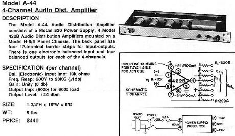
4-chanel audio dist. amplifier
Published:2012/10/18 3:40:00 Author:muriel | Keyword: 4-chanel, audio dist. amplifier
View full Circuit Diagram | Comments | Reading(796)
4-input summing power amplifier
Published:2012/10/18 3:37:00 Author:muriel | Keyword: 4-input, summing power, amplifier

View full Circuit Diagram | Comments | Reading(729)
25hz peaking amplifier
Published:2012/10/18 3:32:00 Author:muriel | Keyword: 25hz, peaking amplifier

View full Circuit Diagram | Comments | Reading(740)
| Pages:40/250 At 202122232425262728293031323334353637383940Under 20 |
Circuit Categories
power supply circuit
Amplifier Circuit
Basic Circuit
LED and Light Circuit
Sensor Circuit
Signal Processing
Electrical Equipment Circuit
Control Circuit
Remote Control Circuit
A/D-D/A Converter Circuit
Audio Circuit
Measuring and Test Circuit
Communication Circuit
Computer-Related Circuit
555 Circuit
Automotive Circuit
Repairing Circuit