
Amplifier Circuit
Index 206
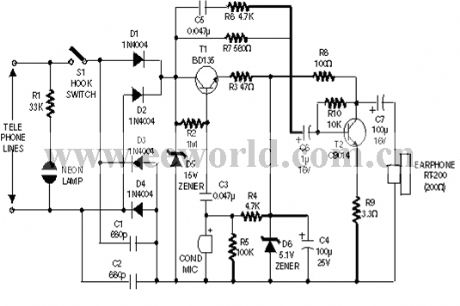
The headphone diode receiving phone
Published:2011/6/3 0:09:00 Author:Seven | Keyword: diode receiving phone
View full Circuit Diagram | Comments | Reading(396)
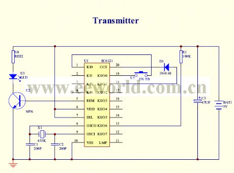
the emitting circuit
Published:2011/6/3 0:07:00 Author:Seven | Keyword: emitting circuit
View full Circuit Diagram | Comments | Reading(374)
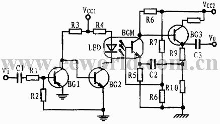
The photocoupler-replaced audio transformer circuit
Published:2011/6/3 0:18:00 Author:Seven | Keyword: audio transformer
View full Circuit Diagram | Comments | Reading(641)
The gas water heater circuit
Published:2011/6/3 0:52:00 Author:Seven | Keyword: gas water heater

View full Circuit Diagram | Comments | Reading(2813)
The thermocouple AD switch circuit
Published:2011/6/3 1:06:00 Author:Seven | Keyword: thermocouple, AD switch circuit
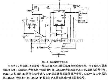
Figure 1-7 the thermocouple temperature control circuitThis is a temperature control circuit of 5V single power supply and 12 bit cold pole compensation, which has the functions of shutting-off. The supervision is done by a J thermocouple. LT1025A is a compensation circuit of the thermocouple cold pole, LTC1050 is the wave-cutting computing amplifier which is used to magnify the signals. The RC net of 47KΩ and 1μF can filter noises when the signal is coming in to the A/D converter. LT1297 is the A/D converter, LTC1257 is the reference power supply, and the output of LTC1257 is the temperature control signal in system supervision. (View)
View full Circuit Diagram | Comments | Reading(907)
The thermocouple temperature/frequency converter circuit
Published:2011/6/3 1:20:00 Author:Seven | Keyword: thermocouple, temperature/frequency converter

The output pulse of I3 drives the DIN-pin of LTCI146, and GNDI is connected with I3. The output of DOUT and TIL are compatible with signals. The maximum consumption current of the circuit is 460μA, and it is allowed to use the 9v power supply. LT1025 is the thermocouple cool pole compensator, LTC1049 is a low-power computing amplifier which contains capacitors, and LTC1146 is an integrated signal separating circuit. (View)
View full Circuit Diagram | Comments | Reading(964)
The thermistor temperature collecting circuit
Published:2011/6/3 1:44:00 Author:Seven | Keyword: thermistor, temperature collecting
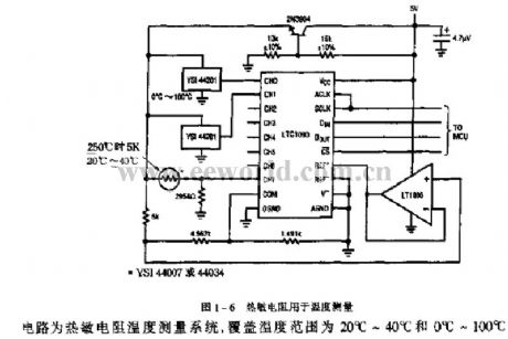
Figure 1-6 the thermistor of temperature measuringThis is a thermistor temperature measuring system, whose covering temperature ranges are 20℃~40℃ and 0℃~100℃. (View)
View full Circuit Diagram | Comments | Reading(503)
The radio circuit of frequency LED display (1)
Published:2011/6/3 23:27:00 Author:Seven | Keyword: radio circuit
View full Circuit Diagram | Comments | Reading(515)
The automobile supervision circuit
Published:2011/6/3 2:21:00 Author:Seven | Keyword: automobile, supervision circuit
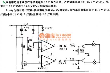
This circuit is used to supervise the automobile power supply of 12V. If the voltage ranges 12~14.5v, it is normal; if the voltage is lower than 12v or higher than 14.5v, there will be indicators glowing. A1 and A2 are the indicator comparator, which are used to adjust the relays of W1 and W2. When the voltage of automobile power supply is higher than 14.5v, the indicator of B is lighting; if it is lower than 12v, the indicator of A is lighting; when it is normal, neither of the indicators is glowing.
(View)
View full Circuit Diagram | Comments | Reading(409)
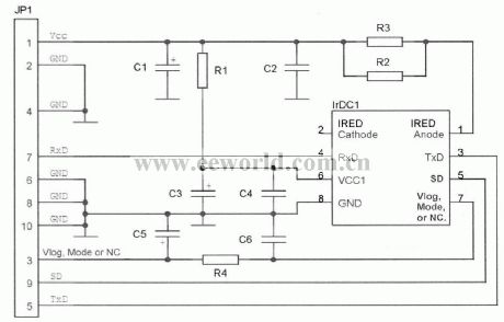
The power supply circuit of infrared emitting/receiving
Published:2011/6/3 0:50:00 Author:Seven | Keyword: power supply, infrared emitting/receiving
View full Circuit Diagram | Comments | Reading(395)
circuit of improving linearity of photoelectric isolation device
Published:2011/6/8 7:09:00 Author:chopper | Keyword: linearity, photoelectric isolation device
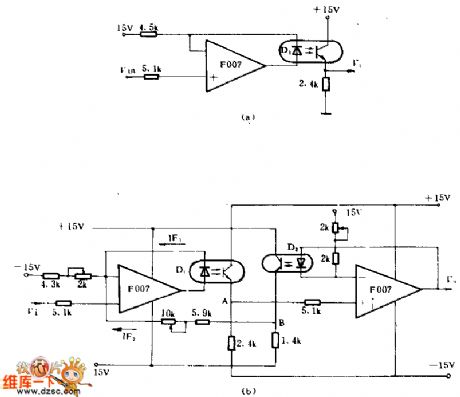
We can improve the linearity of transmission of photoelectric couplers markedly by using inverse feedback.In the picture a,D1 is in the feedback path,the current through D1 will vary linearly with V1 strictly.The shortage of this circuit is that it don't consider the non-linear relation between current transmission of photoelectric couplers and operating current.Thus,careful selection is necessary as well as adjusting device.In the picture b,the circuit adds the second order feedback in order to improve the linearity.The gain frequency of the circuit is between 0~30KHZ,and the dynamic range is -8~+8V,nonlinear distortion(when it is ±8V)is less than 0.5%,weeping sound is less than 1mV,common mode voltage is more than 250V.
(View)
View full Circuit Diagram | Comments | Reading(467)
The voice distress box of patient faintness
Published:2011/6/3 23:47:00 Author:Seven | Keyword: voice distress box, patient faintness

In the figure, the carriage switch SK can be used in mercury switches in the market and self-made mercury or salty water switches, see as figure a. SK is used to test the state of the taker: when it is still, as it is put vertically, the two electric poles are insulated; when the people are moving, the two poles are on and off now and then, which makes VT1 and VT2 conducting and blocked now and then. Therefore, the CI, which is linked with VT2 pole, charges and discharges now and then, but the voltage on C1 can reach 1.3v all the time which is lower than the offset triggering LEV of 1/3 VDD(2v) of the time-based circuit(555).
(View)
View full Circuit Diagram | Comments | Reading(445)
The linear plat temperature adjuster
Published:2011/6/4 0:32:00 Author:Seven | Keyword: temperature adjuster

Notes: Rp is the plat resistance 118MFRTD, *1% thin film resistance. Adjusting process: setting to zero, set the output of the sensor to be 0v when it is 0℃; gain adjusting, set the output voltage of the sensor to be 1v when it is 100℃; linearity adjusting, the output of the sensor is set to be 4V when it is 400℃; adjust repeatedly accordingly. (View)
View full Circuit Diagram | Comments | Reading(454)
The light control toy car of KD-28
Published:2011/6/3 2:37:00 Author:Seven | Keyword: light control, toy car
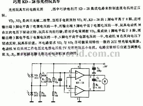
VD1 and VD2 are two light dependent resistors, when VD1 is lighted by a torch, the LEV of the 1-pin of KD-28 is higher than 8-pin, at that moment, the LEV of the output terminal, the 3-pin, is high than the half of the power supply, but the LEV of 5-pin is lower than that, and the toy motor M is rotating forward by the drive of the forward voltage, so the toy car runs forward; if the VD2 is lighted by a torch, the LEV of the 1-pin of the integrated chip is lower than 8-pin, so the LEV of the output terminal,3-pin, is lower than the half of the power supply, and that of 5-pin is higher than half of the power supply, the motor rotates forward.
(View)
View full Circuit Diagram | Comments | Reading(427)
TD-5 ultrasonic micro fogging humidifier
Published:2011/6/5 12:46:00 Author:Seven | Keyword: fogging humidifier

T:Power supply transformer FU:Fuse VT:Triode L1,L2 and L3: inductor B: Piezoelectric pottery power shifter S-N:magnet ring floater SL: water level switch RP1:fog content adjusting potentiometer RP2: adjustable resistor (View)
View full Circuit Diagram | Comments | Reading(1942)
The infrared receiver circuit
Published:2011/6/3 0:37:00 Author:Seven | Keyword: infrared receiver

Because of the integrated amplifier, the circuit in Figure 8.5 is simple and small-sized. It is fixed with a TDA4050 integrated circuit, the weak infrared signal is received by the light dependent diode VD, and the signal is magnified by the NPN firstly. As the condensing (of which the diameter is about 15mm, and the focal length is about 30mm)lens is used here, the effective distance is increased to 20-30 times more than the former. The capacitor C can effectively reduce the low-frequency noise signal in the range of 50-100HZ.
(View)
View full Circuit Diagram | Comments | Reading(626)
The Fahrenheit(F) thermometer circuit
Published:2011/6/3 0:26:00 Author:Seven | Keyword: Fahrenheit(F) thermometer

In the figure, there are two kinds of LM335 and LM336 circuit, whose output voltage UA is 1mv/1F.The potentiometer RP2 on the output terminal of LM336 is adjusted to 2.554v, and RP1 is used to adjust the output voltage.
(View)
View full Circuit Diagram | Comments | Reading(738)
The practical crystal test circuit
Published:2011/6/1 20:33:00 Author:Seven | Keyword: crystal, test circuit


The writer has made a crystal test circuit of 10KHZ~1000MHZ with several simple elements(see as the figure). BG1 and its connected RC form a multi-frequency oscillator, after C3,D1 and D2 test the wave, the LED will get a voltage, and the polarity of the upper part is negative and the lower is positive, which drive the LED glow. If the crystal is broken and the LED is not glow, then we can install the circuit in the repairing power supply and leave two holes for the test elements. Notice: the two wires, which are led out from the crystal, can be too close to each other, or the oscillating amplitude will be reduced and the LED won't glowing.
(View)
View full Circuit Diagram | Comments | Reading(1055)
the sound controlled core circuit
Published:2011/6/3 7:21:00 Author:Seven | Keyword: sound controlled

View full Circuit Diagram | Comments | Reading(449)
The imported electric razor circuit
Published:2011/6/3 6:56:00 Author:Seven | Keyword: electric razor

View full Circuit Diagram | Comments | Reading(1059)
| Pages:206/250 At 20201202203204205206207208209210211212213214215216217218219220Under 20 |
Circuit Categories
power supply circuit
Amplifier Circuit
Basic Circuit
LED and Light Circuit
Sensor Circuit
Signal Processing
Electrical Equipment Circuit
Control Circuit
Remote Control Circuit
A/D-D/A Converter Circuit
Audio Circuit
Measuring and Test Circuit
Communication Circuit
Computer-Related Circuit
555 Circuit
Automotive Circuit
Repairing Circuit