
Amplifier Circuits-Audio
Index 7
ELECTRONIC_EAR_LOW_NOISE_AUDIO_AMPLIFIER_FOR_PAROBOLIC_DISH_MIKES
Published:2009/6/18 23:57:00 Author:May
Use this circuit with a parabolic reflector microphone for eavesdropping on distant sounds. (View)
View full Circuit Diagram | Comments | Reading(1698)
SIMPLE_HIGH_GAIN_AUDIO_AMPLIFIER
Published:2009/6/18 23:53:00 Author:May
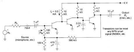
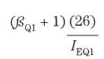
This amplifier has a very high gain in the audio range and is approximately the product of the current gains of the three transistors multiplied by the ratio of RL to (RIN+RS).RIN is approximately to: (View)
View full Circuit Diagram | Comments | Reading(902)
SIMPLE_20_dB_GAIN_AUDIO_AMPLIFIER
Published:2009/6/18 23:49:00 Author:May
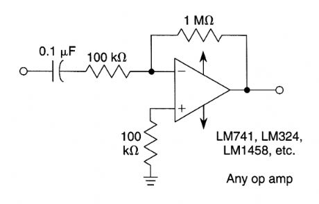
View full Circuit Diagram | Comments | Reading(1293)
LOW_LEVEL_AUDIO_AMPLIFIER
Published:2009/6/18 23:48:00 Author:May

View full Circuit Diagram | Comments | Reading(665)
TRANSISTOR_RIAA_PREAMP_FOR_MAGNETIC_PHONE_CARTRIDGES
Published:2009/6/18 23:42:00 Author:May
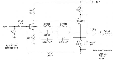
This two-transistor circuit has around 40 dB (midband) gain at 1 kHz. A magnetic cartridge is used as a source. (View)
View full Circuit Diagram | Comments | Reading(1603)
PERSONAL_STEREO_AUDIO_AMP
Published:2009/6/18 23:40:00 Author:May
You can make your personal stereo do double duty as a small room stereo by adding this 2-watt amplifier. (View)
View full Circuit Diagram | Comments | Reading(693)
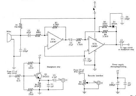
TWO_TRANSISTOR_AUDIO_AMPLIFIER
Published:2009/6/18 23:39:00 Author:May

This is a general-purpose audio ampliffier for driving a pair of stereo earphones in monaural mode.Two can be used for stereo. In this case, ground the centei top of the earphone (sleeve of J1). (View)
View full Circuit Diagram | Comments | Reading(793)
NB_FM_AUDIO_AMPLIFIER
Published:2009/6/18 23:36:00 Author:May

This audio system amplifies, limits, and filters an audio voice signal for use with an FM modulator or VCO. It has pre-emphasis of 6-dB/octave 800-3000Hz. Almost any suitable op amp can be used. (View)
View full Circuit Diagram | Comments | Reading(1894)
AUDIO_AMPLIFIER_WITH_TUNEABLE_FILTER
Published:2009/6/15 23:00:00 Author:May

This audio amplifier can tune from 500 to 1500 Hz and will drive a speaker or headphones. Use-ful for CW reception or other receiver applications, only two IC devices are needed. (View)
View full Circuit Diagram | Comments | Reading(664)
18_W_BRIDGE_AUDIO_AMPLIFIER
Published:2009/6/15 22:18:00 Author:May

Two LM383 IC devices are used in a bridge circuit that is useful for auto sound applications. (View)
View full Circuit Diagram | Comments | Reading(1804)
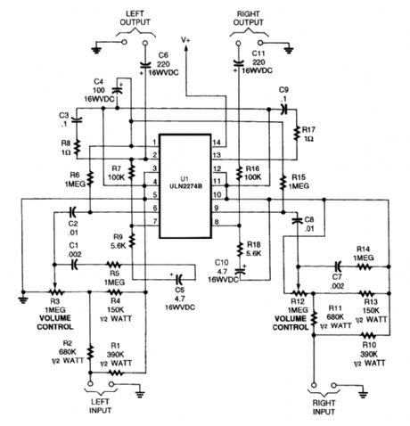
DUAL_AUDIO_AMPLIFIER
Published:2009/6/15 21:53:00 Author:May
View full Circuit Diagram | Comments | Reading(748)
HALF_WATT_SINGLE_CHANNEL_AUDIO_AMPLIFIER
Published:2009/6/15 21:31:00 Author:May
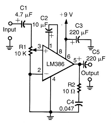
This circuit uses an LM386 IC and will work from 6- to 12-V battery sources. Output is about 0.5 W into 8 Ω. (View)
View full Circuit Diagram | Comments | Reading(716)
SERIES_PARALLEL_LOOP_ALARM
Published:2009/6/14 21:38:00 Author:jailer

Two SCRs are used with two sensor loops. One loop uses series switches, the other loop parallel switches. When a switch actuation occurs, the SCR triggers. The alarm should be a noninterrupting type. (View)
View full Circuit Diagram | Comments | Reading(769)
MULTI_LOOP_PARALLEL_ALARM
Published:2009/6/14 21:35:00 Author:jailer

This alarm has status LEDs connected across each inverter output to indicate the status of its as-sociated sensor. S8 is used to monitor the switches via the LEDs, or to trigger an alarm via Q1 and SCR1. BZ1 should be a suitable alarm of the noninterrupting type. (View)
View full Circuit Diagram | Comments | Reading(674)
HIGH_POWER_ALARM_DRIVER
Published:2009/6/14 21:32:00 Author:jailer

In this circuit, a low-powered SCR is used to trigger a higher powered SCR. When a switch is opening (52, 53, 54) or closing (55, 56, 57), ei-ther SCR1 or SCR2 triggers. This triggers SCR3 via Dl, D2, and R5. BZ1 is a high-powered alarm of the noninterrupting type. (View)
View full Circuit Diagram | Comments | Reading(748)
Wiring circuit diagram of operational amplifier application circuit input
Published:2011/7/16 9:44:00 Author:Sophia | Keyword: Operational amplifier application circuit input, Wiring
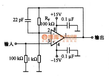
The wiring of op-amp applications circuit inputsThe impedance of Op amp's inverting input and the non-inverting inputare high, the input wiring should be short, otherwise, the external electrostatic and electromagnetic induction will generate noise. Figure is the in-phase amplifier circuit with phase gain of 40dB; the impedance of inverting input is high, if the wiring of this part is too long, which will lead to noise.So feedback resistor RF and Rs should be connected close to the inverting input to make the part of the high-impedance bea short connection. (View)
View full Circuit Diagram | Comments | Reading(796)
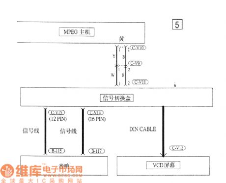
Southeast Ling Sheng audio(VCD) electric system circuit
Published:2011/7/20 21:26:00 Author:leo | Keyword: Audio(VCD), electric system
View full Circuit Diagram | Comments | Reading(612)
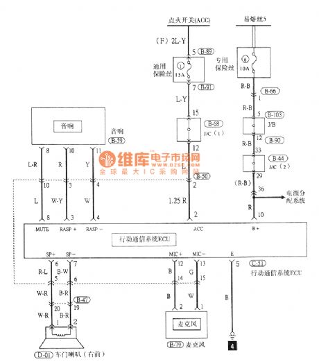
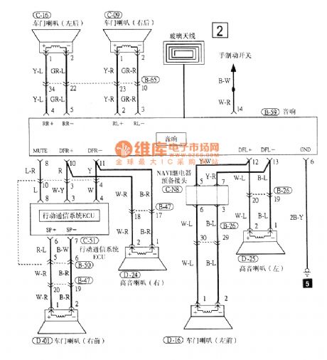
Southeast Ling Sheng audio electric system circuit
Published:2011/7/20 21:28:00 Author:leo | Keyword: Audio, electric system
View full Circuit Diagram | Comments | Reading(562)
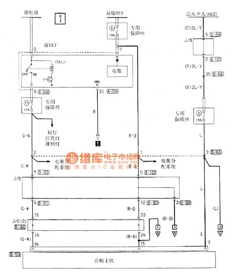
Southeast Ling Sheng speaker electric system circuit
Published:2011/7/20 21:32:00 Author:leo | Keyword: Speaker, electric system

View full Circuit Diagram | Comments | Reading(510)
ULN3814A-The sinle chip audio integrated circuit
Published:2011/7/16 2:53:00 Author:leo | Keyword: Sinle chip, Audio, Integrated circuit
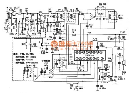
ULN3814A is a kind of integrated circuit used in pocket-sized radio and other kinds of radios.
1.ULN3814A integrated chip inner circuit diagram and pin functions:ULN3814A contains amplitude-modulated oscillator, frequency mixing circuit, frequency-modulating circuit, AGC, AFC, and audio power amplifier as well as voltage-stabilizing circuit.
2.Main parameters of ULN3814A:(1)No-working voltage coverage is from 3 V to 1 V and working voltage coverage is 6 V and 9 V. (2)Output power. Under the condition that Vcc is 7\6 V and R(L) is 8 ohms, the output power is 0.35W. When Vcc is 9 V and R(L) is 8 ohms, the output power is 0.6W.(3)Voltage gain and input resistance. When the voltage gain of the power amplifier is over 40 dB, input resistance is 200kohms. (View)
View full Circuit Diagram | Comments | Reading(799)
| Pages:7/13 12345678910111213 |
Circuit Categories
power supply circuit
Amplifier Circuit
Basic Circuit
LED and Light Circuit
Sensor Circuit
Signal Processing
Electrical Equipment Circuit
Control Circuit
Remote Control Circuit
A/D-D/A Converter Circuit
Audio Circuit
Measuring and Test Circuit
Communication Circuit
Computer-Related Circuit
555 Circuit
Automotive Circuit
Repairing Circuit