A/D-D/A Converter Circuit
Index 20
POWER_VOLTAGE_TO_CURRENT_CONVERTER
Published:2009/6/25 2:17:00 Author:May

Low cost converter is capable of supplying constant ac currents up to 1 A over variable loads. (View)
View full Circuit Diagram | Comments | Reading(0)
CALCULATOR_TO_STOPWATCH_CONVERTER
Published:2009/6/25 2:17:00 Author:May

This circuit can be fitted to any calculator existing with an automatic constant to enable it to be used as a stop-watch. The 555 timer is set to run at a suitable frequency and connected to the existing calculator battery via the push-on push-off switch and the existing calculator on-off switch. (View)
View full Circuit Diagram | Comments | Reading(0)
HI_LO_RESISTANCE_TO_VOLTAGE_CONVERTER
Published:2009/6/25 2:10:00 Author:May
View full Circuit Diagram | Comments | Reading(718)
LOW_COST,μP_INTERFACED,TEMPERATURE_TO_DIGITAL_CONVERTER
Published:2009/6/25 2:09:00 Author:May
View full Circuit Diagram | Comments | Reading(688)
IMPEDANCE_CONVERTER
Published:2009/6/24 23:42:00 Author:May

Used to match 10-megohrninputimpedanceto 50-ohm transmission Iine or 50-ohm input of instruments such as spectrum analyzer, video amplifier, or fre-quency counter. Voltage gain is exactly 0.5. Fre-quency response is from DC to 20 MHz and can be boosted by using higher-frequency transis-tor.-M. J. Salvati, FET Probe Drives 50-Ohm Load, EDN Magazine, March 5, 1973, p 87 and 89. (View)
View full Circuit Diagram | Comments | Reading(0)
WINDSHIELD_WIPER_CONTROLLER
Published:2009/6/24 21:47:00 Author:May

This circuit provides complete speed con-trol over car's windshield wipers. They can be slowed down to any rate even down to four sweeps per minute. The controller has two principal circuits: The rate-determining circuit-a unijunction transistor connected as a freerunning oscillator, and the silicon-controlled rectifier which is the actuator. (View)
View full Circuit Diagram | Comments | Reading(809)
NTSC_TO_RGB_CONVERTER
Published:2009/6/24 21:43:00 Author:May

This circuit takes baseband NTSC video, decodes it, and derives RGB video suitable for driving a color multisync computer monitor. This enables the user to take advantage of the generally better resolution of computer monitors. (View)
View full Circuit Diagram | Comments | Reading(0)
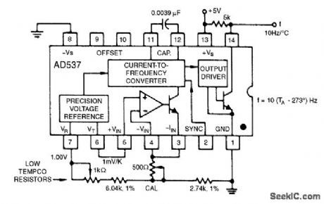
TEMPERATURE_TO_FREQUENCY_CONVERTER_CELSIUS
Published:2009/6/24 4:17:00 Author:May

The 1.00-V reference output can be combined with the 1-mV/°K output to realize various temperature scales. For the Celsius scale, the lower end of the timing resistor must be offset by 273 mV. This is easily accomplished, and it results in an output from 0 to 1 kHz for temperatures from 0℃ to +100℃. Other offsets and scale factors are equally easy to implement. (View)
View full Circuit Diagram | Comments | Reading(0)
TEMPERATURE_TO_FREQUENCY_CONVERTER_KELVIN
Published:2009/6/24 4:17:00 Author:Jessie

This simple connection results in a direct conversion of temperature to frequency. The 1-mV/°K temperature output serves as the input to the buffer amplifier, and the oscillator drive current is scaled to be 298μA at 298°K (+25℃). Use of a 1000-pF capacitor results in a corresponding fre-quency of 2.98 kHz. A single-point trim for calibration is normally sufficient to give errors less than ±2℃ from -55℃ to +125℃. An NPO capacitor is preferred to minimize nonlinearity that results from capacitance drift. (View)
View full Circuit Diagram | Comments | Reading(0)
EIGHT_INPUT_A_D_CONVERTER_FOR_TEMPERATURE_MEASUREMENTS
Published:2009/6/24 4:03:00 Author:May


The actual processing circuitry of this A/D converter consists of only four parts: U2, U3, R1 and R2. Eight temperature probes are used with the circuit; however, they can be replaced with other types of sensors, as long as resistors R3 through R10 are removed.
(View)
View full Circuit Diagram | Comments | Reading(0)
THREE_IC_LOW_COST_A_D_CONVERTER
Published:2009/6/24 1:57:00 Author:May
View full Circuit Diagram | Comments | Reading(837)
HIGH_SPEED_3_BIT_A_D_CONVERTER
Published:2009/6/24 1:55:00 Author:May
View full Circuit Diagram | Comments | Reading(1119)
FAST_PRECISION_A_D_CONVERTER
Published:2009/6/24 1:53:00 Author:May
View full Circuit Diagram | Comments | Reading(733)
3_1_2_DIGIT_A_D_CONVERTER_WITH_LCD_DISPLAY
Published:2009/6/24 1:52:00 Author:May
View full Circuit Diagram | Comments | Reading(1156)
TRACKING_SERVO_TYPE_A_D_CONVERTER
Published:2009/6/24 1:48:00 Author:May
View full Circuit Diagram | Comments | Reading(792)
THREE_DECADE_LOGARITHMIC_A_D_CONVERTER
Published:2009/6/24 1:47:00 Author:May
View full Circuit Diagram | Comments | Reading(1068)
FOUR_CHANNEL_DIGITALLY_MULTIPLEXED_RAMP_A_D_CONVERTER
Published:2009/6/24 1:43:00 Author:May
View full Circuit Diagram | Comments | Reading(747)
8_BIT_SUCCESSIVE_APPROXIMATION_A_D_CONVERTER
Published:2009/6/24 1:42:00 Author:May
View full Circuit Diagram | Comments | Reading(1)
8_BIT_TRACKING_A_D_CONVERTER
Published:2009/6/24 1:41:00 Author:May
View full Circuit Diagram | Comments | Reading(819)
8_BIT_A_D_CONVERTER_1
Published:2009/6/24 1:39:00 Author:May
View full Circuit Diagram | Comments | Reading(1008)
| Pages:20/24 1234567891011121314151617181920Under 20 |
Circuit Categories
power supply circuit
Amplifier Circuit
Basic Circuit
LED and Light Circuit
Sensor Circuit
Signal Processing
Electrical Equipment Circuit
Control Circuit
Remote Control Circuit
A/D-D/A Converter Circuit
Audio Circuit
Measuring and Test Circuit
Communication Circuit
Computer-Related Circuit
555 Circuit
Automotive Circuit
Repairing Circuit


