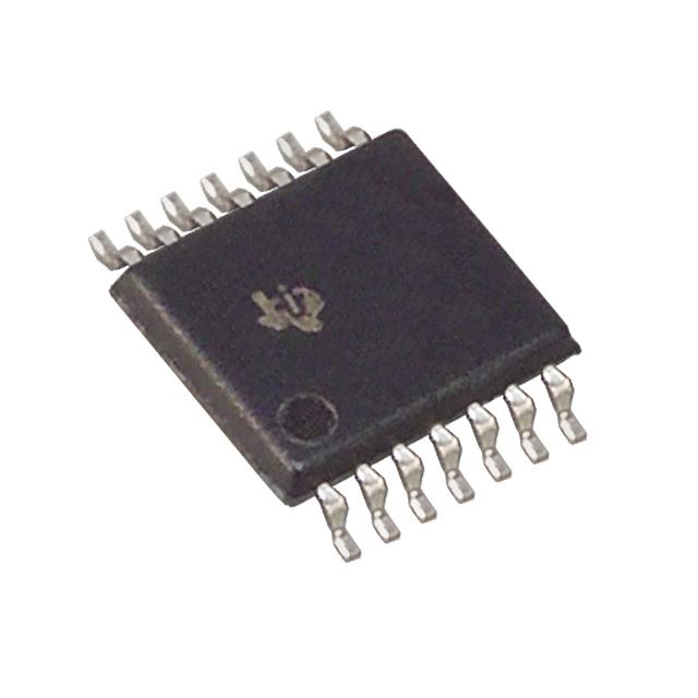
CD74HC14PW, CD74HC14PWG4, CD74HC14PWR
Attentive hint
Want to post a buying lead? If you are not a member yet, please select the specific/related part number first and then fill the quantity and your contact details in the "Request for Quotation Form " on the left, and then click "Send RFQ ".Your buying lead can then be posted, and the reliable suppliers will quote via our online message system or other channels soon.
Datasheet: CD74HC14PWR
File Size: 290849 KB
Manufacturer: TI [Texas Instruments]
Download : Click here to Download
Datasheet: CD74HC14PWR
File Size: 290849 KB
Manufacturer: TI [Texas Instruments]
Download : Click here to Download
CD74HC14PW General Description
The 'HC14 and 'HCT14 each contain six inverting Schmitt triggers in one package.
CD74HC14PW Maximum Ratings
DC Supply Voltage, VCC . . . . . . . . . . . . . . . . . . . . . . . . -0.5V to 7V DC Input Diode Current, IIK For VI < -0.5V or VI > VCC + 0.5V . . . . . . . . . . . . . . . . . . . .±20mA DC Output Diode Current, IOK For VO < -0.5V or VO > VCC + 0.5V . . . . . . . . . . . . . . . . . . ±20mA DC Drain Current, per Output, IO For -0.5V < VO < VCC +0.5V . . . . . . . . . . . . . . . . . . . . . . . .±25mA DC Output Source or Sink Current per Output Pin, IO For VO > -0.5V or VO < VCC + 0.5V . . . . . . . . . . . . . . . . . . ±25mA DC VCC or Ground Current, ICC . . . . . . . . . . . . . . . . . . . . . ±50mA
CD74HC14PW Features
• Unlimited Input Rise and Fall Times • Exceptionally High Noise Immunity • Fanout (Over Temperature Range) - Standard Outputs . . . . . . . . . . . . . . . 10 LSTTL Loads - Bus Driver Outputs . . . . . . . . . . . . . 15 LSTTL Loads • Wide Operating Temperature Range . . . -55oC to 125oC • Balanced Propagation Delay and Transition Times • Significant Power Reduction Compared to LSTTL Logic ICs • HC Types - 2V to 6V Operation - High Noise Immunity: NIL = 30%, NIH = 30% of VCC at VCC = 5V • HCT Types - 4.5V to 5.5V Operation - CMOS Input Compatibility, Il 1A at VOL , VOH
CD74HC14PW Typical Application
· Audio· Automotive· Broadband· Digital Control· Military· Optical Networking· Security· Telephony· Video & Imaging· Wireless
CD74HC14PW Connection Diagram
CD74HC14PWR General Description
The 'HC14 and 'HCT14 each contain six inverting Schmitt triggers in one package.
CD74HC14PWR Maximum Ratings
DC Supply Voltage, VCC . . . . . . . . . . . . . . . . . . . . . . . . -0.5V to 7V DC Input Diode Current, IIK For VI < -0.5V or VI > VCC + 0.5V . . . . . . . . . . . . . . . . . . . .±20mA DC Output Diode Current, IOK For VO < -0.5V or VO > VCC + 0.5V . . . . . . . . . . . . . . . . . . ±20mA DC Drain Current, per Output, IO For -0.5V < VO < VCC +0.5V . . . . . . . . . . . . . . . . . . . . . . . .±25mA DC Output Source or Sink Current per Output Pin, IO For VO > -0.5V or VO < VCC + 0.5V . . . . . . . . . . . . . . . . . . ±25mA DC VCC or Ground Current, ICC . . . . . . . . . . . . . . . . . . . . . ±50mA
CD74HC14PWR Features
• Unlimited Input Rise and Fall Times • Exceptionally High Noise Immunity • Fanout (Over Temperature Range) - Standard Outputs . . . . . . . . . . . . . . . 10 LSTTL Loads - Bus Driver Outputs . . . . . . . . . . . . . 15 LSTTL Loads • Wide Operating Temperature Range . . . -55oC to 125oC • Balanced Propagation Delay and Transition Times • Significant Power Reduction Compared to LSTTL Logic ICs • HC Types - 2V to 6V Operation - High Noise Immunity: NIL = 30%, NIH = 30% of VCC at VCC = 5V • HCT Types - 4.5V to 5.5V Operation - CMOS Input Compatibility, Il 1A at VOL , VOH
CD74HC14PWR Typical Application
· Audio· Automotive· Broadband· Digital Control· Military· Optical Networking· Security· Telephony· Video & Imaging· Wireless
CD74HC14PWR Connection Diagram
Quick search:
A B C D E F G H I J K L M N O P Q R S T U V W X Y Z 0 1 2 3 4 5 6 7 8 9