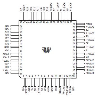
PinoutSpecifications Symbol Description Min Max Units VCC Supply Voltage* 0.3 +7.0 V TSTG Storage Temp 65 +150 C TA Oper Ambient Temp † † C* Voltages on all pins with respect to GND.† See Ordering InformationDescriptionThe Z86193 is a CMOS ROMless Z8...
Z86193: PinoutSpecifications Symbol Description Min Max Units VCC Supply Voltage* 0.3 +7.0 V TSTG Storage Temp 65 +150 C TA Oper Ambient Temp † † C* Voltages on all...
SeekIC Buyer Protection PLUS - newly updated for 2013!
268 Transactions
All payment methods are secure and covered by SeekIC Buyer Protection PLUS.
Symbol | Description | Min | Max | Units |
VCC | Supply Voltage* | 0.3 | +7.0 | V |
TSTG | Storage Temp | 65 | +150 | C |
TA | Oper Ambient Temp | † | † | C |
The Z86193 is a CMOS ROMless Z8® microcontroller enhanced with a hardwired 16-bit x 16-bit multiplier, 32-bit/16-bit divider, three 16-bit counter/timers, search and merge instructions, Evaluation mode and a Bus Request mode. The device is code compatible with other Z8 family devices, yet it offers more powerful mathematical capabilities, data searching capabilities, and bit manipulation. The Z86193 is offered in a 64-pin VQFP package.
The Z86193 provides up to 16 output address lines permitting an address space of up to 64 Kbytes each of Program or Data memory. Eight address outputs are provided by a de-multiplexed 8-bit Address Bus (A7-A0) or by a multiplexed 8-bit Address/Data Bus (AD7-AD0). The remaining eight address lines (A15-A8) can be provided by the software configuration of Port0 to output address. The Z86193 includes a bus which differs from other Z8 devices. The Z86193 provides bus control signals /RD (Read Strobe), /WR (Write Strobe), and ALE (Address Latch Enable).
There are 464 8-bit registers located on-chip and organized as 444 general-purpose registers, 16 control and status registers, one reserved register, and up to three I/O port registers. The Z86193 Register File is partitioned into two Register Pages. Page0 contains 208 registers and Page1 contains 208 registers. The 48 other registers are common to both Register Pages. The Register file is also divided into 29 working register groups of 16 registers each. Configuratio of the registers in this format allows the use of short format instructions. There are 17 additional registers implemented in the Expanded Register file in Banks D and E. Two of the registers may be used as general-purpose, while the other 15 are used to supply data and control for the multiplier/divider unit and the additional counter/timers.