Features: •Fully Integrated PLL•Intelligent Dynamic Clock Switch•LVPECL Clock Outputs•LVCMOS Control I/O•3.3V Operation•32-Lead TQFP PackagingPinoutSpecifications SYMBOL CHARACTERISTICS MIN MAX UNIT CONDITION VCCVINVOUTIINIOUTTS Supply VoltageDC I...
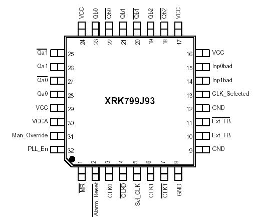
XRK799J93: Features: •Fully Integrated PLL•Intelligent Dynamic Clock Switch•LVPECL Clock Outputs•LVCMOS Control I/O•3.3V Operation•32-Lead TQFP PackagingPinoutSpecifications...
SeekIC Buyer Protection PLUS - newly updated for 2013!
268 Transactions
All payment methods are secure and covered by SeekIC Buyer Protection PLUS.
SYMBOL | CHARACTERISTICS | MIN | MAX | UNIT | CONDITION |
VCC VIN VOUT IIN IOUT TS |
Supply Voltage DC Input Voltage DC Output Voltage DC Input Current DC Output Current Storage Temperature |
-0.3 -0.3 -0.3 -65 |
3.9 VCC+0.3 +20 +50 125 |
V V V mA mA °C |
a.Absolute maximum continuous ratings are those maximum values beyond which damage to the device may occur. Exposure to these conditions or conditions beyond those indicated may adversely affect device reliability. Functional operation at absolute-maximum-rated conditions is not implied.
The XRK799J93 is a PLL clock driver designed specifically for redundant clock tree designs. The device receives two differential LVPECL clock signals from which it generates 5 new differential LVPECL clock outputs. Two of the output pairs regenerate the input signals frequency and phase while the other three pairs generate 2x, phase aligned clock outputs. External PLL feedback is used to also provide zero delay buffer performance.
The XRK799J93 Intelligent Dynamic Clock Switch circuit continuously monitors both input CLK signals. Upon detection of a failure (CLK stuck HIGH or LOW for at least 1 period), the INP_BAD for that CLK will be latched (H). If that CLK is the primary clock, the device will switch to the good secondary clock and phase/frequency alignment will occur with minimal output phase disturbance. The typical phase bump caused by a failed clock is eliminated.