WF128K16

Features: · Access Times of 50, 60, 70, 90, 120 and 150ns· 40 pin Ceramic DIP (Package 303)· Organized as 128Kx16 and 256Kx16· Sector Architecture· 8 equal size sectors of 16KBytes each per chip· Any combination of sectors can be concurrently erased. Also supports full chip erase· 100,000 Erase/Pr...

product image

WF128K16 Picture
SeekIC No. : 004545626 Detail

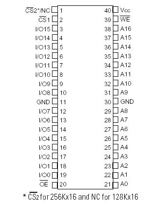
WF128K16: Features: · Access Times of 50, 60, 70, 90, 120 and 150ns· 40 pin Ceramic DIP (Package 303)· Organized as 128Kx16 and 256Kx16· Sector Architecture· 8 equal size sectors of 16KBytes each per chip· An...

floor Price/Ceiling Price

Part Number:
WF128K16
Supply Ability:
5000

Price Break

  • Qty
  • 1~5000
  • Unit Price
  • Negotiable
  • Processing time
  • 15 Days
Total Cost: $ 0.00

SeekIC Buyer Protection PLUS - newly updated for 2013!

  • Escrow Protection.
  • Guaranteed refunds.
  • Secure payments.
  • Learn more >>

Month Sales

268 Transactions

Rating

evaluate  (4.8 stars)

Upload time: 2024/7/26

Payment Methods

All payment methods are secure and covered by SeekIC Buyer Protection PLUS.

Notice: When you place an order, your payment is made to SeekIC and not to your seller. SeekIC only pays the seller after confirming you have received your order. We will also never share your payment details with your seller.
Product Details

Description


Features:

· Access Times of 50, 60, 70, 90, 120 and 150ns
· 40 pin Ceramic DIP (Package 303)
· Organized as 128Kx16 and 256Kx16
· Sector Architecture
· 8 equal size sectors of 16KBytes each per chip
· Any combination of sectors can be concurrently erased. Also supports full chip erase
· 100,000 Erase/Program Cycles Minimum (0°C to 70°C)
· Data Retention, 10 Years at 125°C
· Commercial, Industrial and Military Temperature Ranges
· 5 Volt Programming; 5V ±10% Supply
· Low Power CMOS
· Embedded Erase and Program Algorithms
· TTL Compatible Inputs and CMOS Outputs
· Built-in Decoupling Caps and Multiple Ground Pins for Low Noise Operation
· Page Program Operation and Internal Program Control Time


Pinout

  Connection Diagram


Specifications

Parameter   Unit
Operating Temperature

Supply Voltage Range (VCC)

Signal voltage range (any pin except A9) (2)

Storage Temperature Range

Lead Temperature (soldering, 10 seconds)

Data Retention Mil Temp

Endurance (write/erase cycles) Mil Temp

A9 Voltage for sector protect (VID) (3)
-55 to +125

-2.0 to +7.0

-2.0 to +7.0

-65 to +150

+300

10 years

10,000 cycles min.

-2.0 to +14.0
°C

V

V

°C

°C


V

NOTES:
1. Stresses above the absolute maximum rating may cause permanent damage to the device. Extended operation at the maximum levels may degradeperformance and affect reliability.
2. Minimum DC voltage on input or I/O pins is -0.5V. During voltage transitions, inputs may overshoot VSS to -2.0 V for periods of up to 20ns. Maximum DC voltage on output and I/O pins is VCC + 0.5V. During voltage transitions, outputs may overshoot to Vcc + 2.0 V for periods of up to 20ns.
3. Minimum DC input voltage on A9 pin is -0.5V. During voltage transitions, A9 may overshoot Vss to -2V for periods of up to 20ns. Maximum DC input voltage on A9 is +13.5V which may overshoot to 14.0 V for periods up to 20ns.


Customers Who Bought This Item Also Bought

Margin,quality,low-cost products with low minimum orders. Secure your online payments with SeekIC Buyer Protection.
Cable Assemblies
Potentiometers, Variable Resistors
Circuit Protection
Prototyping Products
DE1
RF and RFID
View more