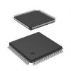
Features: • 36 Input by 37 Output Crosspoint Switch• 3.2Gb/s NRZ Data Bandwidth• Non-Blocking Architecture Broadcast and Multicast Capabilities• LVTTL/2.5V CMOS Control I/O (3.3V tolerant)• Input Signal Activity Monitoring Function• Integrated Signal Equalizatio...
VSC838: Features: • 36 Input by 37 Output Crosspoint Switch• 3.2Gb/s NRZ Data Bandwidth• Non-Blocking Architecture Broadcast and Multicast Capabilities• LVTTL/2.5V CMOS Control I/O (...
SeekIC Buyer Protection PLUS - newly updated for 2013!
268 Transactions
All payment methods are secure and covered by SeekIC Buyer Protection PLUS.
Power Supply Voltage (VCC) Potential to GND ...............-0.5V to +4.0V
LVTTL Input Voltage Applied ....................................-0.5V to VCC+1.0V
ECL Input Voltage Applied ......................................-0.5V to VCC +0.5V
Output Current (IOUT) ................................................................. 50mA
Case Temperature Under Bias (TC) ............................. -55 to + 125
Storage Temperature (TSTG) ....................................... -65 to + 150
NOTE: (1) Caution: Stresses listed under "Absolute Maximum Ratings" may be applied to devices one at a
time without causing permanent damage. Functionality at or exceeding the values listed is not
implied. Exposure to these values for extended periods may affect device reliability.
The VSC838 is a monolithic 36x36 asynchronous crosspoint switch, designed to carry broadband data streams. The VSC838 also has an internal 37th output channel which is used in conjunction with the Activity Monitor to allow in system diagnostics.
A high degree of VSC838 is maintained throughout the chip via fully differential signal paths.
The crosspoint function of VSC838 is based on a multiplexer array architecture. Each data output is driven by a 36:1 multiplexer that can be programmed to one and only one of its 36 inputs. The signal path is unregistered and fully asynchronous, so there are not any restrictions on the phase, frequency, or signal pattern at each input.
Each high-speed output is a fully differential, switched current driver with switchable on-die terminations for maximum signal integrity. Data inputs are terminated on-die through 100Ω impedance between true and complement inputs (see Input Termination section for further details).
A dual mode programming interface is provided that allows programming commands to be sent as serial data or parallel data. Core programming can be random for each port address, or multiple program assignments can be queued and issued simultaneously. The programming may be initialized to a "straight-through" configuration (A0 to Y0, A1 to Y1, etc.) using the INIT pin.
Unused channels may be powered down to allow efficient use of the switch in applications that require only a subset of the channels. Power-down can be accomplished in hardware, via dedicated power pins for pairs of input and output channels, or in software by programming individual unused outputs with a disable code.