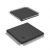
Features: • 34 Input by 34 Output Crosspoint Switch• 2.5 Gbits/sec. NRZ Data Bandwidth• TTL Compatible mP Interface• Differential PECL Data Inputs• On-chip 50W Input Terminations• 50W Source Terminated PECL Output Drivers• Single 3.3V Supply• 14W Max...
VSC835: Features: • 34 Input by 34 Output Crosspoint Switch• 2.5 Gbits/sec. NRZ Data Bandwidth• TTL Compatible mP Interface• Differential PECL Data Inputs• On-chip 50W Input Te...
SeekIC Buyer Protection PLUS - newly updated for 2013!
268 Transactions
All payment methods are secure and covered by SeekIC Buyer Protection PLUS.
Power Supply Voltage (VCC) Potential to GND ..........................-0.5 V to +4.0 V
TTL Input Voltage Applied ................................................... -0.5 V to Vcc+0.5 V
ECL Input Voltage Applied ................................................ -0.5 V to VCC +0.5 V
Output Current (IOUT) ............................................................................ 50 mA
Input Current (IIN) .............................................................................. ±50 mA
VTERM Current (ITERM) ...................................................................... ±800 mA
Case Temperature Under Bias (TC) ...........................................-55 to + 125
Storage Temperature (TSTG) .....................................................-65 to + 150
Note: Caution: Stresses listed under "Absolute Maximum Ratings" may be applied to devices one at a time without causing permanent damage. Functionality at or exceeding the values listed is not implied. Exposure to these values for extended periods may affect device reliability.
The VSC835 is a monolithic 34x34 asynchronous crosspoint switch, designed to carry broadband data streams at up to 2.5 Gbit/s. The non-blocking switch core is programmed through a parallel port interface that allows random access programming of each output port. A high degree of signal integrity is maintained through the chip through fully differential signal paths.
The crosspoint function is based on a multiplexer tree architecture. Each data output is driven by a 34:1 multiplexer tree that can be programmed to one and only one of its 34 inputs, and each data input can be routed to multiple outputs. The signal path is unregistered, so no clock is required for the data inputs. The signal path is asynchronous, so there are no restrictions on the phase, frequency, or signal pattern at each input. Each input channel and each output channel has an signal monitor function that can be used to identify loss of activity (LOA). An interrupt pin is provided to signal LOA, after which an external controller can query the chip to determine the channel(s) on which the fault occurred.
Each output driver is a fully differential switched current driver with on-die back-terminations for maximum signal integrity. Data inputs are terminated on die through 50 ohm resistors terminated to VTERM. The parallel interface uses TTL levels, and provides address, data, and control pins that are compatible with a microprocessor-style interface. The control port provides access to all chip functions, including LOA and programming. Program buffering is provided to allow multiple program assignments to be queued and issued simultaneously via a single configure command.