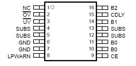
Features: Protects Sensitive Lithium-Ion and Lithium-Polymer Cells from Overcharging and Overdischarging
Used for Two-Cell Battery Packs
No External FETs Required
Provides Protection Against Battery Pack Output Short Circuit
Extremely Low Power Drain on Batteries of About 20 A
Low Internal FET Switch Voltage Drop
User Controllable Delay for Tripping Short Circuit Current Protector
3-A Current CapacityApplicationPDA, Camcorder, Digital Camera, Private Mobile RadioPinout SpecificationsMaximum input voltage (B2, GND) . . . . . . . . . . . . . . . . . . . . . . . . . . . . . . . . . . . . . . . . . . . . . . . . . . . . . . . . . . . . 14 V
Minimum input voltage (B0, GND) . . . . . . . . . . . . . . . . . . . . . . . . . . . . . . . . . . . . . . . . . . . . . . . . . . . . . . . . . . . . 9 V
Maximum charge current (B0, GND) . . . . . . . . . . . . . . . . . . . . . . . . . . . . . . . . . . . . . . . . . . . . . . . . . . . . . . . . . 3.3 A
Minimum discharge current (B0, GND) . . . . . . . . . . . . . . . . . . . . . . . . . . . . . . . . . . . . . . . . . . . . . . . . . . . . . . 3.3 A
Operating junction temperature range, TJ . . . . . . . . . . . . . . . . . . . . . . . . . . . . . . . . . . . . . . . . . . . . 55°C to 150
Storage temperature range Tstg . . . . . . . . . . . . . . . . . . . . . . . . . . . . . . . . . . . . . . . . . . . . . . . . . . . 65°C to 150
Lead Temperature (Soldering, 10 seconds) . . . . . . . . . . . . . . . . . . . . . . . . . . . . . . . . . . . . . . . . . . . . . . . . . . 300
‡ Stresses beyond those listed under "absolute maximum ratings" may cause permanent damage to the device. These are stress ratings only, and functional operation of the device at these or any other conditions beyond those indicated under "recommended operating conditions" is not implied. Exposure to absolute-maximum-rated conditions for extended periods may affect device reliability.
§ All voltages are with respect to ground. Currents are positive into and negative out of the specified terminals.DescriptionThe UCC3911 is a two-cell lithium-ion (Li-Ion) and lithium-polymer (Li-Pol) battery pack protector device that incorporates an on-chip series FET switch thus reducing manufacturing costs and increasing reliability. The device's primary function is to protect both Li-Ion and Li-Pol cells in a two-cell battery pack from being either overcharged (overvoltage) or overdischarged (undervoltage). It employs a precision bandgap voltage reference that is used to detect when either cell is approaching an overvoltage or undervoltage state. When on-board logic detects either condition, the series FET switch opens to protect the cells.
A negative feedback loop controls the FET switch UCC3911 when the battery pack is in either the overvoltage or undervoltage state. In the overvoltage state the action of the feedback loop is to allow only discharge current to pass through the FET switch. In the undervoltage state, only charging current is allowed to flow. The operational amplifier that drives the loop is powered only when in one of these two states. In the undervoltage state the chip enters sleep mode until it senses that the pack is being charged.
The FET switch UCC3911 is driven by a charge pump when the battery pack is in a normally charged state to achieve the lowest possible RDS(on). In this state the negative feedback loop's operational amplifier is powered down to conserve battery power. Short circuit protection for the battery pack is provided and has a nominal delay of 100 s before tripping. An external capacitor may be connected between CDLY and B0 to increase this delay time to allow longer overcurrent transients.
A chip enable (CE) pin is provided that when held low, inhibits normal operation of the device to facilitate assembly of the battery pack.
The UCC3911 is specified for operation over the temperature range of 20°C to 70°C, the typical operating and storage temperature range of Li-Ion and Li-Pol batteries.

 UCC3911-3 Data Sheet


