UCC3580-4

Features: ·Provides Auxiliary Switch Activation Complementary to Main Power Switch Drive·Programmable deadtime (Turn-on Delay) Between Activation of Each Switch·Voltage Mode Control with Feedforward Operation ·Programmable Limits for Both Transformer Volt- Second Product and PWM Duty Cycle·High Cu...

product image

UCC3580-4 Picture
SeekIC No. : 004535960 Detail

UCC3580-4: Features: ·Provides Auxiliary Switch Activation Complementary to Main Power Switch Drive·Programmable deadtime (Turn-on Delay) Between Activation of Each Switch·Voltage Mode Control with Feedforward...

floor Price/Ceiling Price

Part Number:
UCC3580-4
Supply Ability:
5000

Price Break

  • Qty
  • 1~5000
  • Unit Price
  • Negotiable
  • Processing time
  • 15 Days
Total Cost: $ 0.00

SeekIC Buyer Protection PLUS - newly updated for 2013!

  • Escrow Protection.
  • Guaranteed refunds.
  • Secure payments.
  • Learn more >>

Month Sales

268 Transactions

Rating

evaluate  (4.8 stars)

Upload time: 2025/1/6

Payment Methods

All payment methods are secure and covered by SeekIC Buyer Protection PLUS.

Notice: When you place an order, your payment is made to SeekIC and not to your seller. SeekIC only pays the seller after confirming you have received your order. We will also never share your payment details with your seller.
Product Details

Description


Features:

·Provides Auxiliary Switch Activation Complementary to Main Power Switch Drive
·Programmable deadtime (Turn-on Delay) Between Activation of Each Switch
·Voltage Mode Control with Feedforward Operation
·Programmable Limits for Both Transformer Volt- Second Product and PWM Duty Cycle
·High Current Gate Driver for Both Main and Auxiliary Outputs
·Multiple Protection Features with Latched Shutdown and Soft Restart
·Low Supply Current (100 A Startup, 1.5 mA Operation)


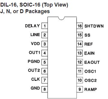
Pinout

  Connection Diagram


Specifications

VDD. . . . . . . . . . . . . . . . . . . . . . . . . . . . . . . . . . . . . . . . . . . 16V
IVDD. . . . . . . . . . . . . . . . . . . . . . . . . . . . . . . . . . . . . . .. . . 25mA
LINE, RAMP . . . . . . . . . . . . . . . . . . . . . .  . . . . 0.3V to VDD + 1V
ILINE, IRAMP . . . . . . . . . . . . . . . . . . . . . . . . . . . . . . . . . . . . 5mA
DELAY . . . . . . . . . . . . . . . . . . . . . . . . . . . . . . . . . . . . . . . . 5.3V
IDELAY . . . . . . . . . . . . . . . . . . . . . . . . . . . . . . . . . . . . . . . . 5mA
IOUT1 (tpw < 1 s and Duty Cycle < 10%) . . . . . . . 0.6A to 1.2A
IOUT2 (tpw < 1 s and Duty Cycle < 10%) . . . . . . . 0.4A to 0.4A
ICLK. . . . . . . . . . . . . . . . . . . . . . . . . . . . . .  . . 100mA to 100mA
OSC1, OSC2, SS, SHTDWN, EAIN . .  . .  . . .  0.3V to REF + 0.3V
IEAOUT. . . . . . . . . . . . . . . . . . . . . . . . . . . . .  . . . . . 5mA to 5mA
IREF . . . . . . . . . . . . . . . . . . . . . . . . . . . . . . . . . . . . . . . . . 30mA
PGND. . . . . . . . . . . . . . . . . . . . . . . . . . . . .  . . . . . . 0.2V to 0.2V
Storage Temperature . . . . . . . . . . . . . . . . .  . . . 65 to +150
Junction Temperature. . . . . . . . . . . . . . . .  . . . . 55 to +150
Lead Temperature (Soldering, 10 sec.) . . . . . . . . . . . . . +300

All voltages are with respect to ground unless otherwise stated. Currents are positive into, negative out of the specified terminal. Consult Packaging Section of Databook for thermal limitations and considerations of packages.


Description

The UCC3580 family of PWM controllers is designed to implement a variety of active clamp/reset and synchronous rectifier switching converter topologies. While containing all the necessary functions for fixed frequency, high performance pulse width modulation, the additional feature of this design UCC3580 is the inclusion of an auxiliary switch driver which complements the main power switch, and with a programmable deadtime or delay between each transition. The active clamp/reset technique allows operation of single ended converters beyond 50% duty cycle while reducing voltage stresses on the switches, and allows a greater flux swing for the power transformer. This approach also allows a reduction in switching losses by recovering energy stored in parasitic elements such as leakage inductance and switch capacitance.

The oscillator UCC3580 is programmed with two resistors and a capacitor to set switching frequency and maximum duty cycle. A separate synchronized ramp provides a voltage feedforward pulse width modulation and a programmed maximum volt-second limit. The generated clock from the oscillator contains both frequency and maximum duty cycle information.


Customers Who Bought This Item Also Bought

Margin,quality,low-cost products with low minimum orders. Secure your online payments with SeekIC Buyer Protection.
Industrial Controls, Meters
Potentiometers, Variable Resistors
Sensors, Transducers
Transformers
Static Control, ESD, Clean Room Products
View more