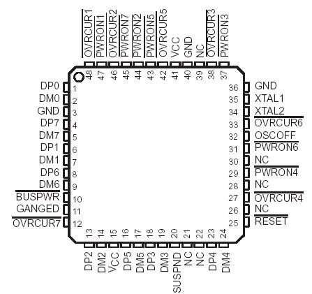
PinoutSpecificationsSupply voltage range, VCC (see Note 1) . . . . . . . . . . . . . . . . . . . . . . . . . . . . .0.5 V to 3.8 VInput voltgage range, VI . . . . . . . . . . . . . . . . . . . . . . . . . . . . . . . . . . .0.5 V to VCC + 0.5 VOutput voltage range, VO . . . . . . . . . . . . . . ....
TUSB2070: PinoutSpecificationsSupply voltage range, VCC (see Note 1) . . . . . . . . . . . . . . . . . . . . . . . . . . . . .0.5 V to 3.8 VInput voltgage range, VI . . . . . . . . . . . . . . . . . . . . . ....
SeekIC Buyer Protection PLUS - newly updated for 2013!
268 Transactions
All payment methods are secure and covered by SeekIC Buyer Protection PLUS.
The TUSB2070 hub is a CMOS device that provides up to seven downstream ports in conformance with the USB specification, version 1.0. It supports two power source modes: bus-powered and self-powered. The hub and downstream ports share the same power source. Per the USB Specification, in the bus-powered mode, only four downstream ports (1-4) are operational, and if all seven ports are desired, the hub must be powered in the self-powered mode. The TUSB2070 hub powers down to 20 nA during the suspend operation by powering down the internal oscillator.
The TUSB2070 hub supports power switching to the downstream ports either individually or ganged. An external device or devices are required to switch power and to detect overcurrent conditions. The TUSB2070 provides outputs to control power switching and inputs to monitor any overcurrent conditions. In the ganged operation, all PWRON signals transition simultaneously and any OVRCUR input may be used.
The hub requires a 48-MHz clock signal to sample data from the upstream port and generate a synchronized 12-MHz USB clock signal. The hub supports the flexibility to use either a 48-MHz oscillator or a crystal tuned to 48-MHz. If an oscillator is used, connect its output to the XTAL1 terminal and leave the XTAL2 terminal open. An oscillator with TTL output may be used if the output does not exceed 3.6 V. For a crystal implementation, use the XTAL1 terminal as the input and the XTAL2 terminal as the feedback path to the crystal. Because the crystal is required to resonate at 48-MHz, a tuning circuit as shown in Figure 6 may be required.
USB-compliant transceivers are provided for the upstream port and all downstream ports. Every downstream port supports both full- and low-speed connection by automatically setting the slew rate according to the speed of the device attached to the port.