Operating Supply Voltage
:
Supply Current
:
Package / Case
:
Peak Wavelength
: 1000 nm
Maximum Operating Temperature
: + 70 C
Minimum Operating Temperature
: 0 C
Packaging
: Tube
Mounting Style
: Through Hole
Features: 256 * 1 Sensor-Element Organization
400 Dots-Per-Inch (DPI) Sensor Pitch
High Linearity and Uniformity
Wide Dynamic Range . . . 4000:1 (72 dB)
Output Referenced to Ground
Low Image Lag . . . 0.5% Typ
Operation to 8 MHz
Single 3-V to 5-V Supply
Rail-to-Rail Output Swing (AO)
No External Load Resistor Required
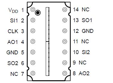
Replacement for TSL1402Pinout SpecificationsSupply voltage range, VDD . . . . . . . . . . . . . . . . . . . . . . . . . . . . . . . . . . . . . . . . . . . . . . . . . . . . . . . . . . . 0.3 V to 6 V
Input voltage range, VI . . . . . . . . . . . . . . . . . . . . . . . . . . . . . . . . . . . . . . . . . . . . . . . . . . . . . . . 0.3 V to VDD + 0.3V
Input clamp current, IIK (VI < 0) or (VI > VDD) . . . . . . . . . . . . . .. . . . . . . . . . . . . . . . . . . . . . . . . . . 20 mA to 20 mA
Output clamp current, IOK (VO < 0 or VO > VDD) . . . . . . . . . . . . . . . . . . . . . . . . . . . . . . . . . . . . . . . 25 mA to 25 mA
Voltage range applied to any output in the high impedance or power-off state, VO . . . . . . . . 0.3 V to VDD + 0.3 V
Continuous output current, IO (VO = 0 to VDD) . . . . . . . . . . . . . . . . . . . . . . . . . . . . . . . . . . . . . . . 25 mA to 25 mA
Continuous current through VDD or GND . . . . . . . . . . . . . . . . . . . . . . . . . . . . . . . . . . . . . . . . . . . . 40 mA to 40 mA
Analog output current range, IO . . . . . . . . . . . . . . . . . . . . . . . . . . . . . . . . . . . . . . . . . . . . . . . . . . 25 mA to 25 mA
Maximum light exposure at 638 nm . . . . . . . . . . . . . . . . . . . . . . . . . . . . . . . . . . . . . . . . . . . . . . . . . . . . . . 5 mJ/cm2
Operating free-air temperature range, TA . . . . . . . . . . . . . . . . . . . . . . . . . . . . . . . . . . . . . . . . . . . . . . 0°C to 70°C
Storage temperature range, Tstg . . . . . . . . . . . . . . . . . . . . . . . . . . . . . . . . . . . . . . . . . . . . . . . . . . 25°C to 85°C
Lead temperature 1,6 mm (1/16 inch) from case for 10 seconds . . . . . . . . . . . . . . . . . . . . . . . . . . . . . . . . . . 260°C
† Stresses beyond those listed under "Absolute Maximum Ratings" may cause permanent damage to the device. These are stress ratings only, and functional operation of the device at these or any other conditions beyond those indicated under "Recommended Operating Conditions" is not implied. Exposure to absolute-maximum-rated conditions for extended periods may affect device reliability.DescriptionThe TSL1402R linear sensor array consists of two sections of 128 photodiodes each and associated charge amplifier circuitry, aligned to form a contiguous 256 × 1 pixel array. The device incorporates a pixel data-hold function that provides simultaneous integration start and stop times for all pixels. The pixels measure 63.5 mm by 55.5 mm, with 63.5-mm center-to-center spacing and 8-mm spacing between pixels. Operation is simplified by internal logic requiring only a serial-input pulse (SI) and a clock.
The TSL1402R is intended for use in a wide variety of applications including mark and code reading, OCR and contact imaging, edge detection and positioning, and optical encoding.

 TSL1402R Data Sheet


