TLE2027I

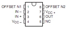
PinoutSpecificationsSupply voltage, VCC+ (see Note 1) . . . . . . . . . . . . . . . . . . . . . . . . . . . . . .. . . . . . .19 VSupply voltage, VCC . . . . . . . . . . . . . . . . . . . . . . . . . . . . . . . . . . . . . . . ... . . . . .-19 VDifferential input voltage, VID (see Note 2) . . . ....

product image

TLE2027I Picture
SeekIC No. : 004520899 Detail

TLE2027I: PinoutSpecificationsSupply voltage, VCC+ (see Note 1) . . . . . . . . . . . . . . . . . . . . . . . . . . . . . .. . . . . . .19 VSupply voltage, VCC . . . . . . . . . . . . . . . . . . . . . . . . ...

floor Price/Ceiling Price

Part Number:
TLE2027I
Supply Ability:
5000

Price Break

  • Qty
  • 1~5000
  • Unit Price
  • Negotiable
  • Processing time
  • 15 Days
Total Cost: $ 0.00

SeekIC Buyer Protection PLUS - newly updated for 2013!

  • Escrow Protection.
  • Guaranteed refunds.
  • Secure payments.
  • Learn more >>

Month Sales

268 Transactions

Rating

evaluate  (4.8 stars)

Upload time: 2025/1/11

Payment Methods

All payment methods are secure and covered by SeekIC Buyer Protection PLUS.

Notice: When you place an order, your payment is made to SeekIC and not to your seller. SeekIC only pays the seller after confirming you have received your order. We will also never share your payment details with your seller.
Product Details

Description


Pinout

  Connection Diagram


Specifications

Supply voltage, VCC+ (see Note 1) . . . . . . . . . . . . . . . . . . . . . . . . . . . . . ..  . . . . . .19 V
Supply voltage, VCC . . . . . . . . . . . . . . . . . . . . . . . . . . . . . . . . . . . . . . . .. . . . . . .-19 V
Differential input voltage, VID (see Note 2) . . . . . . . . . . . . . . . . . . . . . . ..  . .. . . ±1.2 V
Input voltage range, VI (any input) . . . . . . . . . . . . . . . . . . . . . . . . . . . . . . . . . . . .VCC±
Input current, II (each Input) . . . . . . . . . . . . . . . . . . . . . . . . . . . . . . . . . . . . . . . ±1 mA
Output current, IO . . . . . . . . . . . . . . . . . . . . . . . . . . . . . . . . . . . . . . . .  .. . . . . ± 50 mA
Total current into VCC+ . . . . . . . . . . . . . . . . . . . . . . . . . . . . . . . . . . . . .. . . . .. . . 50 mA
Total current out of VCC . . . . . . . . . . . . . . . . . . . . . . . . . . . . . . . . . . . .. . . . . . . 50 mA
Duration of short-circuit current at (or below) 25°C (see Note 3) . . . ..  . . . . .unlimited
Continuous total power dissipation . . . . . . . . . . . . . . . . . See Dissipation Rating Table
Operating free-air temperature range, TA: C suffix . . . . . . . . . . .. . . . . . . .0°C to 70°C
                                                                   I suffix . . . . . . . . . . . . . .. . 40°C to 105°C
                                                                   M suffix . . . . . . . . . . . .  . . 55°C to 125°C
Storage temperature range, Tstg . . . . . . . . . . . . . . . . . . . . . . . . . . .  . 65°C to 150°C
Case temperature for 60 seconds, TC: FK package . . . . . . . . . . . . . . . . . . . . . . .260°C
Lead temperature 1,6 mm (1/16 inch) from case for 10 seconds: D or P packag. 260°C
Lead temperature 1,6 mm (1/16 inch) from case for 60 seconds: JG package.  . .300°C
† Stresses beyond those listed under "absolute maximum ratings" may cause permanent damage to the device. These are stress ratings only, and functional operation of the device at these or any other conditions beyond those indicated under "recommended operating conditions" is not implied. Exposure to absolute-maximum-rated conditions for extended periods may affect device reliability.
NOTES: 1. All voltage values, except differential voltages, are with respect to the midpoint between VCC + and VCC .
             2. Differential voltages are at IN+ with respect to IN. Excessive current flows if a differential input voltage in excess of approximately ±1.2 V is applied between the inputs unless some limiting resistance is used.
             3. The output may be shorted to either supply. Temperature and/or supply voltages must be limited to ensure that the maximum dissipation rating is not exceeded.


Description

The TLE2027I and TLE20x7A contain innovative circuit design expertise and high-quality process control techniques to produce a level of ac performance and dc precision previously unavailable in single operational amplifiers. Manufactured using Texas Instruments state-of-the-art Excalibur process, these devices allow upgrades to systems that use lower-precision devices.

In the area of dc precision, the TLE2027I and TLE20x7A offer maximum offset voltages of 100 µV and 25 µV, respectively, common-mode rejection ratio of 131 dB (typ), supply voltage rejection ratio of 144 dB (typ), and dc gain of 45 V/µV (typ).

The ac performance of the TLE2027I and TLE2037 is highlighted by a typical unity-gain bandwidth specification of 15 MHz, 55° of phase margin, and noise voltage specifications of 3.3 nV/Hz and 2.5 nV/Hz at frequencies of 10 Hz and 1 kHz respectively. The TLE2037 and TLE2037A have been decompensated for faster slew rate (7.5 V/µs, typical) and wider bandwidth (50 MHz). To ensure stability, the TLE2027I and TLE2037A should be operated with a closed-loop gain of 5 or greater.

Both the TLE2027I and TLE20x7A are available in a wide variety of packages, including the industry-standard 8-pin small-outline version for high-density system applications. The C-suffix devices are characterized for operation from 0°C to 70°C. The I-suffix devices are characterized for operation from 40°C to 105°C. The M-suffix devices are characterized for operation over the full military temperature range of 55°C to 125°C.


Customers Who Bought This Item Also Bought

Margin,quality,low-cost products with low minimum orders. Secure your online payments with SeekIC Buyer Protection.
Inductors, Coils, Chokes
Integrated Circuits (ICs)
Optical Inspection Equipment
Fans, Thermal Management
Power Supplies - External/Internal (Off-Board)
Discrete Semiconductor Products
View more