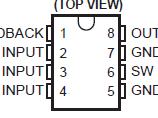
Features: • Internal Step-Up Switching Regulator• Fixed 9-V Output• Charges Battery Source During Transformer-Coupled-Input Operation• Minimum External Components Required (1 Inductor, 1 Capacitor, 1 Diode)• 1- or 2-Cell-Input OperationPinoutSpecificationsInput voltag...
TL496C: Features: • Internal Step-Up Switching Regulator• Fixed 9-V Output• Charges Battery Source During Transformer-Coupled-Input Operation• Minimum External Components Required (1...
SeekIC Buyer Protection PLUS - newly updated for 2013!
268 Transactions
All payment methods are secure and covered by SeekIC Buyer Protection PLUS.
Input voltage, VI: 2C INPUT . . . . . . . . . . . . . . . . . . . . . . . . . . . . . . . . . . . . . . . . . . . . . . . . . . . . . . . . . . . . 3.5 V
1C INPUT . . . . . . . . . . . . . . . . . . . . . . . . . . . . . . . . . . . . . . . . . . . . . . . . . . . . . . . . . . . . . . . 2.5 V
T INPUT . . . . . . . . . . . . . . . . . . . . . . . . . . . . . . . . . . . . . . . . . . . . . . . . . . . . . . . . . . . . . . . . . 20 V
Output voltage, VO (SW) . . . . . . . . . . . . . . . . . . . . . . . . . . . . . . . . . . . . . . . . . . . . . . . . . . . . . . . . . . . . .. . . 12 V
Diode reverse voltage (OUTPUT) . . . . . . . . . . . . . . . . . . . . . . . . . . . . . . . . . . . . . . . . . . . . . . . . . . . . . . . . . 12 V
Switch current (SW) . . . . . . . . . . . . . . . . . . . . . . . . . . . . . . . . . . . . . . . . . . . . . . . . . . . . . . . . . . . . . . .. . . .. 1.2 A
Diode current (OUTPUT) . . . . . . . . . . . . . . . . . . . . . . . . . . . . . . . . . . . . . . . . . . . . . . . . . . . . . . . . . . . . . . . . 1.2 A
Continuous total power dissipation . . . . . . . . . . . . . . . . . . . . . . . . . . . . . . . . . . . . . See Dissipation Rating Table
Operating free-air temperature range, TA . . . . . . . . . . . . . . . . . . . . . . . . . . . . . . . . . . . . . . . . . . . . . . 0 to 70
Storage temperature range, Tstg . . . . . . . . . . . . . . . . . . . . . . . . . . . . . . . . . . . . . . . . . . . . . . . . . .65 to 150
Lead temperature 1,6 mm (1/16 inch) from case for 10 seconds . . . . . . . . . . . . . . . . . . . . . . . . . . . . . . . 260
† Stresses beyond those listed under "absolute maximum ratings" may cause permanent damage to the device. These are stress ratings only, and functional operation of the device at these or any other conditions beyond those indicated under "recommended operating conditions" is not implied. Exposure to absolute-maximum-rated conditions for extended periods may affect device reliability.
The TL496C power-supply control circuit is designed to provide a 9-V regulated supply from a variety of input sources. Operable from a 1- or 2-cell battery input, the TL496C performs as a switching regulator with the addition of a single inductor and filter capacitor. When ac coupled with a step-down transformer, the TL496C operates as a series regulator to maintain the regulated output voltage and, with the addition of a single catch diode, time shares to recharge the input batteries.
The design of the TL496C allows minimal supply current drain during standby operation (125 mA typical). With most battery sources, this allows a constant bias to be maintained on the power supply. This makes power instantly available to the system, thus eliminating power-up sequencing problems.