TL431BC

ApplicationThe TL431 is a programmable precision reference which is used in a variety of ways. It serves as a reference voltage in circuits where a nonstandard reference voltage is needed. Other uses include feedback control for driving an optocoupler in power supplies, voltage monitor, constant c...

product image

TL431BC Picture
SeekIC No. : 004520163 Detail

TL431BC: ApplicationThe TL431 is a programmable precision reference which is used in a variety of ways. It serves as a reference voltage in circuits where a nonstandard reference voltage is needed. Other use...

floor Price/Ceiling Price

Part Number:
TL431BC
Supply Ability:
5000

Price Break

  • Qty
  • 1~5000
  • Unit Price
  • Negotiable
  • Processing time
  • 15 Days
Total Cost: $ 0.00

SeekIC Buyer Protection PLUS - newly updated for 2013!

  • Escrow Protection.
  • Guaranteed refunds.
  • Secure payments.
  • Learn more >>

Month Sales

268 Transactions

Rating

evaluate  (4.8 stars)

Upload time: 2025/1/11

Payment Methods

All payment methods are secure and covered by SeekIC Buyer Protection PLUS.

Notice: When you place an order, your payment is made to SeekIC and not to your seller. SeekIC only pays the seller after confirming you have received your order. We will also never share your payment details with your seller.
Product Details

Description


Application

The TL431 is a programmable precision reference which is used in a variety of ways. It serves as a reference voltage in circuits where a nonstandard reference voltage is needed. Other uses include feedback control for driving an optocoupler in power supplies, voltage monitor, constant current source, constant current sink and series pass regulator. In each of these applications, it is critical to
maintain stability of the device at various operating currents and load capacitances. In some cases the circuit designer can estimate the stabilization capacitance from the stability boundary conditions curve provided in Figure 15. However, these typical curves only provide stability information at specific cathode voltages and at a specific load condition. Additional information is needed to determine the capacitance needed to optimize phase margin or allow for process variation.

A simplified model of the TL431 is shown in Figure 31. When tested for stability boundaries, the load resistance is 150. The model reference input consists of an input transistor and a dc emitter resistance connected to the device anode. A dependent current source, Gm, develops a current whose amplidute is determined by the difference between the 1.78 V internal reference voltage source and the input transistor emitter voltage. A portion of Gm flows through compensation capacitance, CP2. The voltage across CP2 drives the output dependent current source, Go, which is connected across the device cathode and anode.
  Model component values are:
  Vref = 1.78 V
  Gm = 0.3 + 2.7 exp (IC/26 mA)
where IC is the device cathode current and Gm is in mhos
  Go = 1.25 (Vcp2) µmhos.

Resistor and capacitor typical values are shown on the model. Process tolerances are ±20% for resistors, ±10% for capacitors, and ±40% for transconductances.

An examination of the device model reveals the location of circuit poles and zeroes:
  Connection Diagram
  Connection Diagram
In addition, there is an external circuit pole defined by the load:
  Connection Diagram
Also, the transfer dc voltage gain of the TL431 is:
   G=GMRGMGoRL
Example 1:
IC=10 mA,RL= 230 ,CL= 0. Define the transfer gain.
  The DC gain is:
   G = GMRGMGoRL=(2.138)(1.0 M)(1.25 )(230) = 615= 56 dB
  Connection Diagram
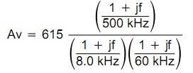
The resulting transfer function Bode plot is shown in Figure 32. The asymptotic plot may be expressed as the following equation:
  Connection Diagram
The Bode plot shows a unity gain crossover frequency of approximately 600 kHz. The phase margin, calculated from the equation, would be 55.9 degrees. This model matches the OpenLoop Bode Plot of Figure 12. The total loop would have a unity gain frequency of about 300 kHz with a phase margin of about 44 degrees.


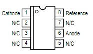
Pinout

  Connection Diagram


Specifications

Rating Symbol Value Unit
Cathode to Anode Voltage VKA 37 V
Cathode Current Range, Continuous IK 100 to +150 mA
Reference Input Current Range, Continuous Iref 0.05 to +10 mA
Operating Junction Temperature TJ 150 °C
Operating Ambient Temperature Range
   TL431I, TL431AI, TL431BI
   TL431C, TL431AC, TL431BC
TA

40 to +85
0 to +70

°C
Storage Temperature Range Tstg 65 to +150 °C
Total Power Dissipation @ TA = 25°C
   Derate above 25°C Ambient Temperature
   D, LP Suffix Plastic Package
   P Suffix Plastic Package
   DM Suffix Plastic Package
PD 0.70
1.10
0.52
W
Total Power Dissipation @ TC = 25°C
   Derate above 25°C Case Temperature
   D, LP Suffix Plastic Package
   P Suffix Plastic Package
PD 1.5
3.0
W


Customers Who Bought This Item Also Bought

Margin,quality,low-cost products with low minimum orders. Secure your online payments with SeekIC Buyer Protection.
Undefined Category
Crystals and Oscillators
Tapes, Adhesives
803
View more