TL384x

PinoutSpecificationsSupply voltage (see Note 1) (ICC < 30 mA) . . . . . . . . . . . . . . . . . Self limiting Analog input voltage range, VI (VFB and ISENSE) . . . . . .. . . . 0.3 V to 6.3 V Output voltage, VO (OUTPUT) . . . . . . . . . . . . . . . . . . . . . . . . . . . . . . . . . 35 V Inpu...

product image

TL384x Picture
SeekIC No. : 004520141 Detail

TL384x: PinoutSpecificationsSupply voltage (see Note 1) (ICC < 30 mA) . . . . . . . . . . . . . . . . . Self limiting Analog input voltage range, VI (VFB and ISENSE) . . . . . .. . . . 0.3 V to 6.3 V Out...

floor Price/Ceiling Price

Part Number:
TL384x
Supply Ability:
5000

Price Break

  • Qty
  • 1~5000
  • Unit Price
  • Negotiable
  • Processing time
  • 15 Days
Total Cost: $ 0.00

SeekIC Buyer Protection PLUS - newly updated for 2013!

  • Escrow Protection.
  • Guaranteed refunds.
  • Secure payments.
  • Learn more >>

Month Sales

268 Transactions

Rating

evaluate  (4.8 stars)

Upload time: 2025/1/11

Payment Methods

All payment methods are secure and covered by SeekIC Buyer Protection PLUS.

Notice: When you place an order, your payment is made to SeekIC and not to your seller. SeekIC only pays the seller after confirming you have received your order. We will also never share your payment details with your seller.
Product Details

Description


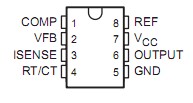
Pinout

  Connection Diagram


Specifications

Supply voltage (see Note 1) (ICC < 30 mA) . . . . . . . . . . . . . . . . . Self limiting
Analog input voltage range, VI (VFB and ISENSE) . . . . . .. . . . 0.3 V to 6.3 V
Output voltage, VO (OUTPUT) . . . . . . . . . . . . . . . . . . . . . . . . . . . . . . . . . 35 V
Input voltage, VI, (VC, D package only) . . . . . . . . . . . . . . .. . . . . . . . . . . 35 V
Supply current, ICC . . . . . . . . .. . . . . . . . . . . . . . . . . . . . . . . . . . . . . . . 30 mA
Output current, IO . . . . . . . . . . . . . . . . . . . . . . . . . . . . . . . . . . . . . . .. . . ±1 A
Error amplifier output sink current . . . . . . . . . . . . . . . . . . . . . . . . . . . . 10 mA
Package thermal impedance, JA (see Notes 2 and 3): D package . .  86°C/W 
                                                                                     D-8 package . 97°C/W
                                                                                     P package . . . 85°C/W
Virtual junction temperature range, TJ . . . . . . . . . . . . . . . .. . . . 0°C to 150°C
Output energy (capacitive load) . . . . . . . . . .. . . . . . . . . . . . . . . . . . . . . . 5 µJ
Lead temperature, 1,6 mm (1/16 inch) from case for 10 seconds .. . . . 260°C
Storage temperature range, Tstg . . . . . . . . . . . . . . . . . . . .  . 65°C to 150°C
† Stresses beyond those listed under "absolute maximum ratings" may cause permanent damage to the device. These are stress ratings only, and functional operation of the device at these or any other conditions beyond those indicated under "recommended operating conditions" is not implied. Exposure to absolute-maximum-rated conditions for extended periods may affect device reliability.
NOTES: 1. All voltages are with respect to the device GND terminal.
             2. Maximum power dissipation is a function of TJ(max), JA, and TA. The maximum allowable power dissipation at any allowable ambient temperature is PD = (TJ(max) TA)/JA. Operating at the absolute maximum TJ of 150°C can impact reliability.
             3. The package thermal impedance is calculated in accordance with JESD 51.


Description

The TL284x and TL384x series of control integrated circuits provide the features that are necessary to implement off-line or dc-to-dc fixed-frequency current-mode control schemes with a minimum number of external components. Some of the internally implemented circuits are an undervoltage lockout (UVLO), featuring a start-up current of less than 1 mA, and a precision reference trimmed for accuracy at the error amplifier input. Other internal circuits include logic to ensure latched operation, a pulse-width modulation (PWM) comparator (which also provides current-limit control), and a totem-pole output stage designed to source or sink high-peak current. The output stage, suitable for driving N-channel MOSFETs, is low when it is in the off state.

Major differences between members of these TL284x and TL384x series are the UVLO thresholds and maximum duty-cycle ranges. Typical UVLO thresholds of 16 V (on) and 10 V (off) on the TLx842 and TLx844 devices make them ideally suited to off-line applications. The corresponding typical thresholds for the TLx843 and TLx845 devices are 8.4 V (on) and 7.6 V (off). The TLx842 and TLx843 devices can operate to duty cycles approaching 100%. A duty-cycle range of 0 to 50% is obtained by the TLx844 and TLx845 by the addition of an internal toggle flip-flop, which blanks the output off every other clock cycle.

The TL284x-series devices are characterized for operation from 40°C to 85°C. The TL384x-series devices are characterized for operation from 0°C to 70°C.


Customers Who Bought This Item Also Bought

Margin,quality,low-cost products with low minimum orders. Secure your online payments with SeekIC Buyer Protection.