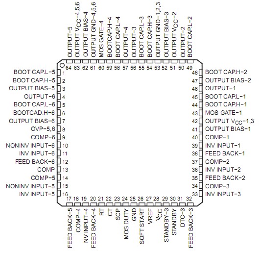
TL1466I

PinoutSpecificationsSupply voltage, VCC (see Note 1) . . . . . . . . . . . . . . . . . . . . . . . . . . . . . . . . . . . . . . . . . . . . . . . . . . . . . . . . . 13 VInput voltage, VI at OVP, COMP . . . . . . . . . . . . . . . . . . . . . . . . . . . . . . . . . . . . . . . . . . . . . . . . ...

product image

TL1466I Picture
SeekIC No. : 004520053 Detail

TL1466I: PinoutSpecificationsSupply voltage, VCC (see Note 1) . . . . . . . . . . . . . . . . . . . . . . . . . . . . . . . . . . . . . . . . . . . . . . . . . . . . . . . . . 13 VInput voltage, VI at OVP, C...

floor Price/Ceiling Price

Part Number:
TL1466I
Supply Ability:
5000

Price Break

  • Qty
  • 1~5000
  • Unit Price
  • Negotiable
  • Processing time
  • 15 Days
Total Cost: $ 0.00

SeekIC Buyer Protection PLUS - newly updated for 2013!

  • Escrow Protection.
  • Guaranteed refunds.
  • Secure payments.
  • Learn more >>

Month Sales

268 Transactions

Rating

evaluate  (4.8 stars)

Upload time: 2024/5/31

Payment Methods

All payment methods are secure and covered by SeekIC Buyer Protection PLUS.

Notice: When you place an order, your payment is made to SeekIC and not to your seller. SeekIC only pays the seller after confirming you have received your order. We will also never share your payment details with your seller.
Product Details

Description


Pinout

  Connection Diagram


Specifications

Supply voltage, VCC (see Note 1)   . . . . . . . . . . . . . . . . . . . . . . . . . . . . . . . . . . . . . . . . . . . . . . . . . . . . . . . . . 13 V
Input voltage, VI at OVP, COMP   . . . . . . . . . . . . . . . . . . . . . . . . . . . . . . . . . . . . . . . . . . . . . . . . . . . . . . . . . . 13 V
Error amplifier input voltage, V(AMP)  . . . . . . . . . . . . . . . . . . . . . . . . . . . . . . . . . . . . . . . . . . . . . . . . . . . . . . . 13 V
Output voltage, VO  . . . . . . . . . . . . . . . . . . . . . . . . . . . . . . . . . . . . . . . . . . . . . . . . . . . . . . . . . . . . . . . . . . . . 13 V
Peak output sink current, I(SINK)  . . . . . . . . . . . . . . . . . . . . . . . . . . . . . . . . . . . . . . . . . . . . . . . . . . . . . . . 100 mA
Peak output source current, I(SOURCE)  . . . . . . . . . . . . . . . . . . . . . . . . . . . . . . . . . . . . . . . . . . . . . . . . . . . −0.5 A
Continuous power total dissipation at (or below) 25°C free-air temperature (see Note 2)   . . . . . .  . . 1785 mW
Operating free-air temperature range, TA  . . . . . . . . . . . . . . . . . . . . . . . . . . . . . . . . . . . . . . . . . . −20°C to 75°C
Storage temperature range, Tstg  . . . . . . . . . . . . . . . . . . . . . . . . . . . . . . . . . . . . . . . . . . . . . . . . −65°C to 150°C
Lead temperature 1,6 mm (1/16 inch) from case for 10 seconds   . . . . . . . . . . . . . . . . . . . . . . . . . . . . . . . 260°C
† Stresses beyond those listed under "absolute maximum ratings" may cause permanent damage to the device. These are stress ratings only, and functional operation of the device at these or any other conditions beyond those indicated under "recommended operating conditions" is not implied. Exposure to absolute-maximum-rated conditions for extended periods may affect device reliability.
NOTES: 1. All voltages are with respect to GND.
             2. Device mounted on a 50 mm * 1.6 mm, fFR4 printed-circuit board.


Description

The TL1466I is a six channel pulse-width-modulation (PWM) control circuit. This device contains reference voltage with a precision of ±2%, a triangle wave oscillator capable of high frequency oscillation up to 0.8 MHz, various protection circuitry, and shutdown circuitry. The output regulation voltage for each channel is set by an external resistor divider. Moreover, the output stage is capable of driving a PNP power transistor with high speed. The high frequency/efficiency switching operation eliminates switching loss by using internal over-drive circuitry at the rising edge and with reverse bias connecting external bootstrap capacitor at the falling edge.

The MOSFET can be used in parallel with the output diode at channel 1 and 4. This results in further high efficiency operation replacing the constant time with this MOSFET when the output diode is turned on. Furthermore, it operates 2.5 V supply voltage and balances switching current by switching repeatedly at the reverse phase with two pairs (channel 1, 4, 6, and 2, 3, 5) of the six channels. The oscillator output of channel 1, 4, and 6 is reverse phase for channel 2, 3, and 5. As a result of these features, this device is well-suited for power supply of portable systems in battery-powered equipment.


Customers Who Bought This Item Also Bought

Margin,quality,low-cost products with low minimum orders. Secure your online payments with SeekIC Buyer Protection.
Circuit Protection
Test Equipment
Memory Cards, Modules
Fans, Thermal Management
Motors, Solenoids, Driver Boards/Modules
View more