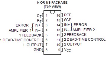
PinoutSpecificationsSupply voltage, VCC (see Note 1) . . . . . . . . . . . . . . . . . . . . . . . . . . . . . . . . . . . . . . . . . . . . 41 VAmplifier input voltage . . . . . . . . . . . . . . . . . . . . . . . . . . . . . . . . . . . . . . . . . . . . . .. . . . . . . 20 VCollector output vol...
TL1453C: PinoutSpecificationsSupply voltage, VCC (see Note 1) . . . . . . . . . . . . . . . . . . . . . . . . . . . . . . . . . . . . . . . . . . . . 41 VAmplifier input voltage . . . . . . . . . . . . . . ....
SeekIC Buyer Protection PLUS - newly updated for 2013!
268 Transactions
All payment methods are secure and covered by SeekIC Buyer Protection PLUS.
The TL1453C incorporates the functions required in the construction of two pulse-width-modulation control circuits on a single monolithic chip. Designed primarily for power supply control, the TL1453C contains an on-chip 2.5-V regulator, two error amplifiers, an adjustable oscillator, two dead-time comparators, undervoltage lockout circuitry, and dual common-emitter output transistor circuits.
The uncommitted output transistors provide common-emitter output capability for each controller. The internal amplifiers exhibit a common-mode voltage range from 1.05 V to 1.45 V. The dead-time control comparator has no offset unless externally altered and may be used to provide 0% to 100% dead time. The on-chip oscillator may be operated by terminating RT (pin 2) and CT (pin 1). During low-VCC conditions, the undervoltage lockout control circuit feature inhibits the output until the internal circuitry is operational.
The TL1453C is characterized for operation from 20°C to 85°C.