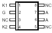
TISPPBL2SD

PinoutSpecifications RATING SYMBOL VALUE UNIT Repetitive peak off-state voltage, IG = 0, -40°C TJ 85°C VDRM -100 V Repetitive peak gate-cathode voltage, VKA = 0, -40°C TJ 85°C VGKRM -90 V Non-repetitive peak on-state pulse current (see Notes 1 and 2)10/1000 µs (Bel...

product image

TISPPBL2SD Picture
SeekIC No. : 004519581 Detail

TISPPBL2SD: PinoutSpecifications RATING SYMBOL VALUE UNIT Repetitive peak off-state voltage, IG = 0, -40°C TJ 85°C VDRM -100 V Repetitive peak gate-cathode voltage, VKA = 0, -40°C TJ 85°C ...

floor Price/Ceiling Price

Part Number:
TISPPBL2SD
Supply Ability:
5000

Price Break

  • Qty
  • 1~5000
  • Unit Price
  • Negotiable
  • Processing time
  • 15 Days
Total Cost: $ 0.00

SeekIC Buyer Protection PLUS - newly updated for 2013!

  • Escrow Protection.
  • Guaranteed refunds.
  • Secure payments.
  • Learn more >>

Month Sales

268 Transactions

Rating

evaluate  (4.8 stars)

Upload time: 2025/1/11

Payment Methods

All payment methods are secure and covered by SeekIC Buyer Protection PLUS.

Notice: When you place an order, your payment is made to SeekIC and not to your seller. SeekIC only pays the seller after confirming you have received your order. We will also never share your payment details with your seller.
Product Details

Description


Pinout

  Connection Diagram


Specifications

RATING SYMBOL VALUE UNIT
Repetitive peak off-state voltage, IG = 0, -40°C TJ 85°C VDRM -100 V
Repetitive peak gate-cathode voltage, VKA = 0, -40°C TJ 85°C VGKRM -90 V
Non-repetitive peak on-state pulse current (see Notes 1 and 2)
           10/1000 µs (Bellcore GR-1089-CORE, Issue 1, November 1994, Section 4)
           0.2/310 µs (I3124, open-circuit voltage wave shape 0.5/700 µs)
           5/310 µs (ITU-T K20 & K21, open-circuit voltage wave shape 10/700 µs)
           1/20 µs (ITU-T K22, open-circuit voltage wave shape 1.2/50 µs)
           2/10 µs (Bellcore GR-1089-CORE, Issue 1, November 1994, Section 4)
ITSP 30
40
40
100
100
A
Non-repetitive peak on-state current, 50/60 Hz (see Notes 1 and 2)
         100 ms
         1 s
         5 s
         300 s
         900 s
ITSM 11
4.5
2.4
0.95
0.93
A
Non-repetitive peak gate current,1/2 µs pulse,cathodes commoned(see Note1) IGSM 40 A
Operating free-air temperature range TA -40to+85 °C
Junction temperature TJ -40to+150 °C
Storage temperature range Tstg -40to+150 °C


Description

The TISPPBL2S is a dual forward-conducting buffered p-gate overvoltage protector. It is designed to protect the Ericsson Components PBL 3xxx family of SLICs (Subscriber Line Interface Circuits) against overvoltages on the telephone line caused by lightning, a.c. power contact and induction. The TISPPBL2S limits voltages that exceed the SLIC supply rail levels.

The SLIC line driver section TISPPBL2S is typically powered from 0 V (ground) and a negative voltage in the region of -10 V to -85 V. The protector gate is connected to this negative supply. This references the protection (clipping) voltage to the negative supply voltage. As the protection voltage will track the negative supply
voltage the overvoltage stress on the SLIC is minimised.

Positive overvoltages TISPPBL2S are clipped to ground by diode forward conduction. Negative overvoltages are initially clipped close to the SLIC negative supply rail value. If sufficient current is available from the overvoltage, then the protector will crowbar into a low voltage ground referenced on-state condition. As the overvoltagesubsides the high holding current of the crowbar prevents d.c. latchup. The TISPPBL2S buffered gate design reduces the loading on the SLIC supply during overvoltages caused by power cross and induction.

These monolithic protection devices TISPPBL2S are fabricated in ion-implanted planar vertical power structures for high reliability and in normal system operation they are virtually transparent. The TISPPBL2S is the TISPPBL2D with a different pinout. The feed-through Ring (leads 4 - 5) and Tip (leads 1 - 8) connections have been replaced by single Ring (lead 4) and Tip (lead 1) connections. This increases package creepage distance of the biased to ground connections from about 0.7 mm to over 3 mm.


Customers Who Bought This Item Also Bought

Margin,quality,low-cost products with low minimum orders. Secure your online payments with SeekIC Buyer Protection.
Potentiometers, Variable Resistors
Circuit Protection
Programmers, Development Systems
Line Protection, Backups
LED Products
View more