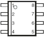
PinoutSpecifications RATING SYMBOL VALUE UNIT Repetitive peak off-state voltage, IG = 0 VDRM -130 V Repetitive peak gate-cathode voltage, VKA = 0 VGKRM -120 V Non-repetitive peak on-state pulse current, (see Notes 1 and 2)10/1000 µs (Bellcore GR-1089-CORE, Issue 1, Nov...
TISP6NTP2B: PinoutSpecifications RATING SYMBOL VALUE UNIT Repetitive peak off-state voltage, IG = 0 VDRM -130 V Repetitive peak gate-cathode voltage, VKA = 0 VGKRM -120 V Non-repetitive p...
SeekIC Buyer Protection PLUS - newly updated for 2013!
268 Transactions
All payment methods are secure and covered by SeekIC Buyer Protection PLUS.
PinoutSpecifications Rating Symbol Value Unit Repetitive peak off-state voltage...
PinoutSpecifications RATING SYMBOL VALUE UNIT Repetitive peak off-state voltage ( 0°C &...
RATING | SYMBOL | VALUE | UNIT |
Repetitive peak off-state voltage, IG = 0 | VDRM | -130 | V |
Repetitive peak gate-cathode voltage, VKA = 0 | VGKRM | -120 | V |
Non-repetitive peak on-state pulse current, (see Notes 1 and 2) 10/1000 µs (Bellcore GR-1089-CORE, Issue 1, November 1994, Section 4) 0.2/310 µs (I3124, open-circuit voltage wave shape 0.5/700 µs) 5/310 µs (ITU-T K.20 & K.21, open-circuit voltage wave shape 10/700 µs) 8/20 µs (IEC 61000-4-5:1995, open-circuit voltage wave shape 1.2/50 µs) 2/10 µs (Bellcore GR-1089-CORE, Issue 1, November 1994, Section 4) |
ITSP | 20 25 25 60 70 |
A |
Non-repetitive peak on-state current, 50/60 Hz (see Notes 1 and 2) 100 ms 1 s 5 s 300 s 900 s |
ITSM | 7 2.7 1.5 0.45 0.43 |
A |
Non-repetitive peak gate current,1/2 µs pulse,cathodes commoned(see Note1) | IGSM | 25 | A |
Operating free-air temperature range | TA | -40to+85 | °C |
Junction temperature | TJ | -40to+150 | °C |
Storage temperature range | Tstg | -65to+150 | °C |
The TISP6NTP2B has an array of four buffered P-gate forward conducting thyristors with twin commoned gates and a common anode connection. Each thyristor cathode has a separate terminal connection. An antiparallel anode-cathode diode is connected across each thyristor. The buffer transistors reduce the gate supply current.
In use, the cathodes of an TISP6NTP2B thyristors are connected to the four conductors to be protected (see Figure 2 and Figure 3). Each gate is connected to the appropriate negative voltage feed. The anode of the TISP6NTP2B is connected to the system common. The TISP6NTP2B is in an 8-pin small-outline surface mount package.
Positive overvoltages are clipped to common by forward conduction of the TISP6NTP2B antiparallel diode. In Figure 2, a negative overvoltage draws a current through the 6.8 Ω resistor and the voltage developed triggers the thyristor on. In Figure 3, negative overvoltages are initially clipped close to the negative supply by emitter follower action of the TISP6NTP2B buffer transistor. If sufficient clipping current flows, the TISP6NTP2B thyristor will regenerate and switch into a low voltage on-state condition. As the negative overvoltage subsides, the high holding current of the TISP6NTP2B prevents d.c. latchup.