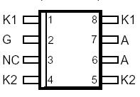
PinoutSpecifications RATING SYMBOL VALUE UNIT Repetitive peak off-state voltage, IG = 0, -40°C TJ 85°C VDRM -100 V Repetitive peak gate-cathode voltage, VKA = 0, -40°C TJ 85°C VGKRM -85 V Non-repetitive peak on-state pulse current (see Notes 1 and 2) 1...
TISP61089: PinoutSpecifications RATING SYMBOL VALUE UNIT Repetitive peak off-state voltage, IG = 0, -40°C TJ 85°C VDRM -100 V Repetitive peak gate-cathode voltage, VKA = 0, -40°...
SeekIC Buyer Protection PLUS - newly updated for 2013!
268 Transactions
All payment methods are secure and covered by SeekIC Buyer Protection PLUS.
PinoutSpecifications Rating Symbol Value Unit Repetitive peak off-state voltage...
PinoutSpecifications RATING SYMBOL VALUE UNIT Repetitive peak off-state voltage ( 0°C &...
RATING |
SYMBOL |
VALUE |
UNIT |
Repetitive peak off-state voltage, IG = 0, -40°C TJ 85°C |
VDRM |
-100 |
V |
Repetitive peak gate-cathode voltage, VKA = 0, -40°C TJ 85°C |
VGKRM |
-85 |
V |
Non-repetitive peak on-state pulse current (see Notes 1 and 2) 10/1000 µs (Bellcore GR-1089-CORE, Issue 1, November 1994, Section 4) 5/320 µs (ITU-T recommendation K20 & K21, open-circuit voltage wave shape 10/700) 1.2/50 µs (Bellcore GR-1089-CORE, Issue 1, November 1994, Section 4, Alternative) 100 2/10 µs (Bellcore GR-1089-CORE, Issue 1, November 1994, Section 4) |
ITSP |
30 40 100 120 |
A |
Non-repetitive peak on-state current, 60 Hz (see Notes 1 and 2) 0.1 s 1 s 5 s 300 s 900 s |
ITSM |
11 |
A |
Non-repetitive peak gate current, 1/2 µs pulse, cathodes commoned (see Notes 1 and 2) |
IGSM |
10 |
A |
Operating free-air temperature range |
TA |
-40 to +85 |
°C |
Junction temperature |
TJ |
-40 to +150 |
°C |
Storage temperature range |
Tstg |
-40 to +150 |
°C |
The TISP61089 is a dual forward-conducting buffered p-gate overvoltage protector. It is designed to protect monolithic SLICs (Subscriber Line Interface Circuits) against overvoltages on the telephone line caused by lightning, a.c. power contact and induction. The TISP61089 limits voltages that exceed the SLIC supply rail voltage. The TISP61089 parameters are specified to allow equipment compliance with Bellcore GR-1089-CORE, Issue 1.
The SLIC line driver section is typically powered from 0 V (ground) and a negative voltage in the region of -10 V to -75 V. The protector gate is connected to this negative supply. This references the protection (clipping) voltage to the negative supply voltage. As the protection voltage will then track the negative supply voltage the overvoltage stress on the SLIC is minimised.
Positive overvoltages are clipped to ground by diode forward conduction. Negative overvoltages are initially clipped close to the SLIC negative supply rail value. If sufficient current is available from the overvoltage, then the protector will crowbar into a low voltage on-state condition. As the overvoltage subsides the high holding current of the crowbar prevents d.c. latchup.
The TISP61089 is intended to be used with a series combination of a 25 or higher resistance and a suitable overcurrent protector. Power fault compliance requires the series overcurrent element to open-circuit or become high impedance (see Applications Information). For equipment compliant to ITU-T recommendations K20 or K21 only, the series resistor value is set by the power cross requirements. For K20 and K21, a minimum series resistor value of 10 is recommended
.
These monolithic protection devices are fabricated in ion-implanted planar vertical power structures for high reliability and in normal system operation they are virtually transparent. The TISP61089 buffered gate design reduces the loading on the SLIC supply during overvoltages caused by power cross and induction. The TISP61089 is available in 8-pin plastic small-outline surface mount package and 8-pin plastic dual-in-linepackage.