THS1240

Features: 40-MSPS Sample Rate12-Bit ResolutionNo Missing CodesOn-Chip Sample and Hold77-dB Spurious Free Dynamic Range at fIN = 15.5 MHz5-V Analog and Digital Supply3-V and 5-V CMOS Compatible Digital Output10.4 Bit ENOB at fIN = 31 MHz65 dB SNR at fIN = 15.5 MHz120-MHz BandwidthInternal or Extern...

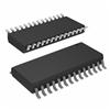
product image

THS1240 Picture
SeekIC No. : 004518826 Detail

THS1240: Features: 40-MSPS Sample Rate12-Bit ResolutionNo Missing CodesOn-Chip Sample and Hold77-dB Spurious Free Dynamic Range at fIN = 15.5 MHz5-V Analog and Digital Supply3-V and 5-V CMOS Compatible Digit...

floor Price/Ceiling Price

Part Number:
THS1240
Supply Ability:
5000

Price Break

  • Qty
  • 1~5000
  • Unit Price
  • Negotiable
  • Processing time
  • 15 Days
Total Cost: $ 0.00

SeekIC Buyer Protection PLUS - newly updated for 2013!

  • Escrow Protection.
  • Guaranteed refunds.
  • Secure payments.
  • Learn more >>

Month Sales

268 Transactions

Rating

evaluate  (4.8 stars)

Upload time: 2025/1/12

Payment Methods

All payment methods are secure and covered by SeekIC Buyer Protection PLUS.

Notice: When you place an order, your payment is made to SeekIC and not to your seller. SeekIC only pays the seller after confirming you have received your order. We will also never share your payment details with your seller.
Product Details

Description


Features:

40-MSPS Sample Rate
12-Bit Resolution
No Missing Codes
On-Chip Sample and Hold
77-dB Spurious Free Dynamic Range at fIN = 15.5 MHz
5-V Analog and Digital Supply
3-V and 5-V CMOS Compatible Digital Output
10.4 Bit ENOB at fIN = 31 MHz
65 dB SNR at fIN = 15.5 MHz
120-MHz Bandwidth
Internal or External Reference
Buffered Differential Analog Input
2s Complement Digital Outputs
Typical 380 mW Power Consumption
Single-Ended or Differential Low-Level Clock Input


Application

Wireless Local Loop
Wireless Internet Access
Cable Modem Receivers
Medical Ultrasound
Magnetic Resonant Imaging


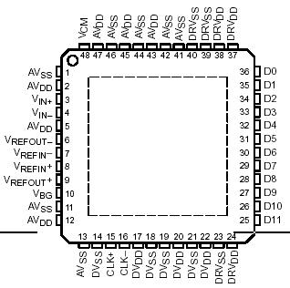
Pinout

  Connection Diagram


Specifications

Supply voltage range: AVDD  . . . . . . . . . . . . . . . . 0.5 V to 7 V
DVDD . . . . . . . . . . . . . . . . . . . . . . . . . . . . . . . . . . 0.5 V to 7 V 
DRVDD  . . . . . . . . . . . . . . . . . . . . . . . . . . . . . . . . 0.5 V to 7 V
Voltage between AVSS and DVSS and DRVSS  . . . .0.3 V to 0.5 V
Voltage between DRVDD and DVDD. . . . . . . . . . . . .0.5 V to 5 V
Voltage between AVDD and DVDD  . . . . . . . . . . . . . 0.5 V to 5 V
Digital data output  . . . . . . . . . . . . . . . . . . . . . . . . . 0.3 V to DVDD+0.3 V
CLK peak input current, Ip(CLK) . . . . . . . . . . . . . . . . . . . . . . . . . . . .20 mA
Peak total input current (all inputs), Ip . . . . . . . . . . . . . . . . . . . . .  30 mA
Operating free-air temperature range, TA:THS1240C . . . . . . . . 0°C to 70°C 
THS1240I  . . . . . . . . . . . . . . . . . . . . . . . . . . . . . . . . . . . . . . . . . 40°C to 85°C
Storage temperature range  . . . . . . . . . . . . . . . . . . . . . . . . . . . 65°C to 150°C
Lead temperature 1,6 mm (1/16 inch) from the case for 10 seconds  . . . . .260°C


Description

The THS1240 is a high-speed low noise 12-bit CMOS pipelined analog-to-digital converter. A differential sample and hold minimizes even order harmonics and allows for a high degree of common mode rejection at the analog input. A buffered analog input of THS1240 enables operation with a constant analog input impedance, and prevents transient voltage spikes from feeding backward to the analog input source. Full temperature DNL performance allows for industrial application with the assurance of no missing codes. The THS1240 can operate with either internal or external references. Internal reference usage selection is accomplished simply by externally connecting reference output terminals to reference input terminals.

The THS1240 uses a differential pipeline architecture and assures no missing codes over the full operating temperature range. The device uses a 1 bit per stage architecture in order to achieve the highest possible bandwidth. The differential analog inputs of THS1240 are terminated with a 1-kΩ resistor. The inputs are then fed to a unity gain buffer followed by the S/H (sample and hold) stage. This S/H stage is a switched capacitor operational amplifier-based circuit, see Figure 3. The pipeline is a typical 1 bit per stage pipeline as shown in the functional block diagram. The digital output of the 12 stages is sent to a digital correction logic block which then outputs the final 12 bits.


Customers Who Bought This Item Also Bought

Margin,quality,low-cost products with low minimum orders. Secure your online payments with SeekIC Buyer Protection.
Semiconductor Modules
Inductors, Coils, Chokes
Isolators
View more