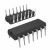
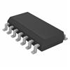
Mounting Style
: SMD/SMT
Polarity
: Non-Inverting
Input Type
: Single-Ended
Output Type
: Single-Ended
Packaging
: Tube
Number of Circuits
: 8
Logic Type
: D-Type Flip-Flop
High Level Output Current
: - 0.4 mA
Low Level Output Current
: 8 mA
Maximum Operating Temperature
: + 70 C
Logic Family
: 74LS
Propagation Delay Time
: 27 ns
Supply Voltage - Max
: 5.25 V
Package / Case
: SOIC-20
DescriptionThe SN74LS273DW is designed as a high-speed 8-bit register. The register consists of eight D-type flip-flops with a common clock and an asynchronous active LOW master reset. This device is supplied in a 20-pin package featuring 0.3 inch lead spacing.
SN74LS273DW has four features. (1)8-bit high speed register. (2)Parallel register. (3)Common clock and master reset. (4)Input clamp diodes limit high-speed termination effects. Those are all the main features.
Some guaranteed operating ratings and absolute maximum ratings SN74LS273DW have been concluded into several points as follow. (1)Its supply voltage would be min 4.75V and typ 5.0V and max 5.25V. (2)Its operating ambient temperature range would be min 0°C to 25°C and max 70°C. (3)Its output current high would be max -0.4mA. (4)Its output current low would be max 8.0mA. It should be noted that stresses above those listed in absolute maximum ratings may cause permanent damage to device.
Also some electrical characteristics SN74LS273DW are concluded as follow. (1)Its input high voltage would be min 2.0V. (2)Its input low voltage would be max 0.8V. (3)Its input clamp diode voltage would be typ -0.65V and max -1.5V. (4)Its output high voltage would be min 2.7V and typ 3.5V. (5)Its output low voltage would be typ 0.25V and max 0.4V at Iol=4.0mA and would be typ 0.35V and max 0.5V at Iol=8.0mA. (6)Its input high current would be max 20uA at Vin=2.7V and would be max 0.1mA at Vin=7.0V. (7)Its input low current would be max -0.4mA at Vin=0.4V. (8)Its short circuit current would be min -20mA and max -100mA. (9)Its power supply current would be max 27mA. (10)Its maximum input clock frequency would be min 30MHz and typ 40MHz. (11)Its propagation delay, /MR to Q output would be typ 18ns and max 27ns. (12)Its propagation delay, clock to output would be typ 17ns and max 27ns. And so on. If you have any question or suggestion or want to know more information please contact us for details. Thank you!

 SN74LS273DW Data Sheet


