Maximum Power Dissipation
:
Elements per Chip
: 2
Logic Type
: Monostable Multivibrator
Package / Case
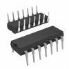
: PDIP-16
Packaging
: Tube
Low Level Output Current
: 8 mA
Logic Family
: LS
High Level Output Current
: - 0.4 mA
Supply Voltage - Max
: 5.25 V
Supply Voltage - Min
: 4.75 V
Maximum Operating Temperature
: + 70 C
Minimum Operating Temperature
: 0 C
Propagation Delay Time
: 80 ns
Features: • SN74LS221 is a Dual Highly Stable One-Shot
• Overriding Clear Terminates Output Pulse
• Pin Out is Identical to SN74LS123Pinout Description
Each multivibrator of the LS221 features a negative-transitiontriggered input and a positive-transition-triggered input either of which can be used as an inhibit input.
Pulse triggering occurs at a voltage level and is not related to the transition time of the input pulse. Schmitt-trigger input circuitry for B input allows jitter-free triggering for inputs as slow as 1 volt /second, providing the circuit with excellent noise immunity. A high immunity to VCC noise is also provided by internal latching circuitry.
Once triggered, the outputs are independent of further transitions of the inputs and are a function of the timing components. The output pulses can be terminated by the overriding clear. Input pulse width may be of any duration relative to the output pulse width. Output pulse width may be varied from 35 nanoseconds to a maximum of 70 s by choosing appropriate timing components. With Rext = 2.0 kW and Cext = 0, a typical output pulse of 30 nanoseconds is achieved. Output rise and fall times are independent of pulse length.
Pulse width stability is achieved through internal compensation and is virtually independent of VCC and temperature. In most applications, pulse stability will only be limited by the accuracy of external timing components.
Jitter-free operation is maintained over the full temperature and VCC ranges for greater than six decades of timing capacitance (10 pF to 10 mF), and greater than one decade of timing resistance (2.0 to 100 kW for the SN74LS221). Pulse width is defined by the relationship: tw(out) = CextRext ln 2.0 9 0.7 Cext Rext; where tW is in ns if Cext is in pF and Rext is in kW. If pulse cutoff is not critical, capacitance up to 1000 mF and resistance as low as 1.4 kW may be used. The range of jitter-free pulse widths is extended if VCC is 5.0 V and 25°C temperature.
Parameters: | Technical/Catalog Information | SN74LS221N |
| Vendor | Texas Instruments |
| Category | Integrated Circuits (ICs) |
| Logic Type | Monostable |
| Independent Circuits | 2 |
| Voltage - Supply | 4.75 V ~ 5.25 V |
| Mounting Type | Through Hole |
| Package / Case | 16-DIP (300 mil) |
| Packaging | Tube |
| Operating Temperature | 0°C ~ 70°C |
| Propagation Delay | 44ns |
| Current - Output High, Low | 400A, 8mA |
| Schmitt Trigger Input | Yes |
| Drawing Number | 296; 4040049; N; 14, 16, 18, 20 |
| Lead Free Status | Lead Free |
| RoHS Status | RoHS Compliant |
| Other Names | SN74LS221N
SN74LS221N
296 3674 5 ND
29636745ND
296-3674-5
|

 SN74LS221N Data Sheet


