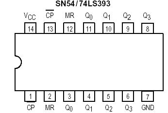
PinoutDescriptionEach half of the SN54/74LS393 operates in the Modulo 16 binary sequence, as indicated in the ÷16 Truth Table. The first flip-flop is triggered by HIGH-to-LOW transitions of the CP input signal. Each of the other flip-flops is triggered by a HIGH-to-LOW transition of the Q output o...
SN54/74LS393: PinoutDescriptionEach half of the SN54/74LS393 operates in the Modulo 16 binary sequence, as indicated in the ÷16 Truth Table. The first flip-flop is triggered by HIGH-to-LOW transitions of the CP i...
SeekIC Buyer Protection PLUS - newly updated for 2013!
268 Transactions
All payment methods are secure and covered by SeekIC Buyer Protection PLUS.
Features: PinoutSpecificationsDescriptionThe SN54/74LS147 and SN54/74LS148 are Priority Encoders. ...
PinoutDescriptionThe LS155 and LS156 are Dual 1-of-4 Decoder/Demultiplexers with common Address in...
Each half of the SN54/74LS393 operates in the Modulo 16 binary sequence, as indicated in the ÷16 Truth Table. The first flip-flop is triggered by HIGH-to-LOW transitions of the CP input signal. Each of the other flip-flops is triggered by a HIGH-to-LOW transition of the Q output of the preceding flip-flop. Thus state changes of the Q outputs do not occur simultaneously. This means that logic signals derived from combinations of these outputs of SN54/74LS393 will be subject to decoding spikes and, therefore, should not be used as clocks for other counters, registers or flip-flops. A HIGH signal on MR forces all outputs to the LOW state and prevents counting.
Each half of the SN54/74LS393 contains a ÷5 section that is independent except for the common MR function. The ÷5section operates in 4.2.1 binary sequence, as shown in the ÷5 Truth Table, with the third stage output exhibiting a 20% duty cycle when the input frequency is constant. To obtain a ÷10 function having a 50% duty cycle output, connect the input signal to CP1 and connect the Q3 output to the CP0 input; the Q0 output provides the desired 50% duty cycle output. If the input frequency is connected to CP0 and the Q0 output is connected to CP1, a decade divider operating in the 8.4.2.1 BCD code is obtained, as shown in the BCD Truth Table. Since the flip-flops change state asynchronously, logic signals derived from combinations of LS390 outputs are also subject to decoding spikes. A HIGH signal on MR forces all outputs LOW and prevents counting.