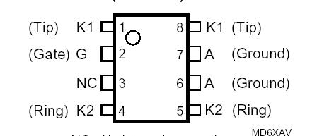
Features: · PBA 3357/3 DCLIC Overvoltage Protector· Dual Voltage-Programmable Protector - Wide 0 to -70 V Programming Range - Low Voltage Overshoot Crowbar and Diode - Low 5 mA max. Triggering Current - Does not Charge Gate Supply - Specified for 0°C to 70°C Operation - Plastic Dual-in-line Packag...
R3612: Features: · PBA 3357/3 DCLIC Overvoltage Protector· Dual Voltage-Programmable Protector - Wide 0 to -70 V Programming Range - Low Voltage Overshoot Crowbar and Diode - Low 5 mA max. Triggering Curre...
SeekIC Buyer Protection PLUS - newly updated for 2013!
268 Transactions
All payment methods are secure and covered by SeekIC Buyer Protection PLUS.
RATING |
SYMBOL |
VALUE |
UNIT |
Non-repetitive peak off-state voltage, IG = 0, 0°C TJ 70°C Repetitive peak off-state voltage, IG = 0, 0°C TJ 70°C Repetitive peak gate-cathode voltage, VKA = 0, 0°C TJ 70°C |
VDSM VDRM VGKRM |
-90 -80 -80 |
V V V |
Non-repetitive peak on-state pulse current (see Notes 1 and 2) 10/1000 µs (Bellcore TR-NWT-001089, Section 4 and Appendix A) 0.2/310 µs (RLM88, open-circuit voltage wave shape 1.5 kV 0.5/700 µs) 5/310 µs (CCITT K17, K20 & K21, open-circuit voltage wave shape 1.5 kV 10/700 µs)) 2/10 µs (Bellcore TR-NWT-001089, Section 4 and Appendix A) |
ITSP |
30 38 38 80 |
A |
Non-repetitive peak on-state current, 50 Hz (see Notes 1 and 2) 200 ms 1 s 25 s 900 s |
ITSM |
5.6 3.5 0.7 0.42 |
A |
Non-repetitive peak gate current, 1/2 µs,(see Notes 1 and 2) Junction temperature Storage temperature range |
IGSM TJ Tstg |
25 -55 to +150 -55 to +150 |
A °C °C |
The R3612 is a dual forward-conducting buffered p-gate over voltage protector in a plastic DIP package. It is designed to protect the Ericsson Components PBA 3357/3 DCLIC (Dual Channel Complete Line Interface Circuit) against over voltages on the telephone line caused by lightning, a.c. power contact and induction. The R3612 limits voltages that exceed the DCLIC supply rail voltage.
The DCLIC line driver section is powered from 0 V (ground) and a negative voltage in the region of -44 V to -56 V. The protector gate is connected to this negative supply. This references the protection (clipping) voltage to the negative supply voltage. As the protection voltage will track the negative supply voltage the over voltage stress on the DCLIC is minimised.
Positive over voltages of R3612 are clipped to ground by a low voltage overshoot diode. Negative over voltages are initially clipped close to the DCLIC negative supply rail value. If sufficient current is available from the over voltage, then the protector will crowbar into a low voltage on-state condition. As the over voltage subsides the high holding current of the crowbar prevents d.c. latchup.
The buffered gate design reduces the loading on the DCLIC supply during over voltages caused by power cross and induction. The gate characteristic is designed to produce a net current drain on the interface circuit voltage supply during low level power cross or induction.
This removes the need for a separate clamping
diode across the voltage supply.
These monolithic protection devices are fabricated in ion-implanted planar vertical power structures for high reliability and in normal system operation they are virtually transparent. Characteristic values for the R3612 are measured either at the extremes of the DCLIC recommended operating voltage range (-44 V to -56 V) or at the DCLIC maximum rated supply voltage (-70 V).