PEF2256

Features: • High-density, generic interface for all E1/T1/J1 applications• Analog receive and transmit circuits for long-haul and short-haul applications• E1 or T1/J1 mode selectable• Data and clock recovery using an integrated digital phase-locked loop• Maximum line ...

product image

PEF2256 Picture
SeekIC No. : 004459496 Detail

PEF2256: Features: • High-density, generic interface for all E1/T1/J1 applications• Analog receive and transmit circuits for long-haul and short-haul applications• E1 or T1/J1 mode selectab...

floor Price/Ceiling Price

Part Number:
PEF2256
Supply Ability:
5000

Price Break

  • Qty
  • 1~5000
  • Unit Price
  • Negotiable
  • Processing time
  • 15 Days
Total Cost: $ 0.00

SeekIC Buyer Protection PLUS - newly updated for 2013!

  • Escrow Protection.
  • Guaranteed refunds.
  • Secure payments.
  • Learn more >>

Month Sales

268 Transactions

Rating

evaluate  (4.8 stars)

Upload time: 2024/11/25

Payment Methods

All payment methods are secure and covered by SeekIC Buyer Protection PLUS.

Notice: When you place an order, your payment is made to SeekIC and not to your seller. SeekIC only pays the seller after confirming you have received your order. We will also never share your payment details with your seller.
Product Details

Description


Features:

• High-density, generic interface for all E1/T1/J1 applications
• Analog receive and transmit circuits for long-haul and short-haul applications
• E1 or T1/J1 mode selectable
• Data and clock recovery using an integrated digital phase-locked loop
• Maximum line attenuation up to -43 dB at 1024 kHz (E1) and up to -36 dB at 772 kHz (T1/J1)
• Programmable receive equalizer characteristic
• Software-selectable receive line termination
• Programmable transmit pulse shapes for E1 and T1/J1 pulse masks
• Programmable line build-out for CSU signals according to ANSI T1. 403 and FCC68: 0dB, -7.5 dB,
-15 dB, -22.5 dB (T1/J1)
• Low transmitter output impedances for high transmit return loss
• Tristate function of the analog transmit line outputs
• Analog switch for redundancy applications
• Transmit line monitor protecting the device from damage
• Receive line monitor mode
• Jitter specifications of ITU-T I.431, G.703, G.736 (E1), G.823 (E1) and AT&T TR62411 (T1/J1) are met
• Crystal-less wander and jitter attenuation/compensation
• Common master clock reference for E1 and T1/J1 (any frequency within 1.02 and 20 MHz)
• Power-down function
• Support of automatic protection switching
• Dual-rail or single-rail digital inputs and outputs
• Unipolar NRZ or CMI for interfacing fiber-optical transmission routes
• Selectable line codes (E1: HDB3, AMI/T1: B8ZS, AMI with ZCS)
• Loss-of-signal indication with programmable thresholds according to ITU-T G.775, ETS300233 (E1) and ANSI T1.403 (T1/J1)
• Optional data stream muting upon LOS detection
• Programmable receive slicer threshold
• Clock generator for jitter-free system/transmit clocks per channel
• Local loop and remote loop for diagnostic purposes
• Low power device
• Single power supply (3.3 V) or dual power supply (3.3 V and 1.8 V)
• Frame alignment/synthesis for 2048 kbit/s according to ITU-T G.704 (E1) and for
1544 kbit/s according to ITU-T G.704 and JT G.704 (T1/J1)
• Programmable frame formats:
E1: Doubleframe, CRC multiframe (E1)
T1: 4-frame multiframe (F4,FT), 12-frame multiframe (F12, D3/4), extended
superframe (F24, ESF), remote switch mode (F72, SLC96)
• Selectable conditions for recover/loss of frame alignment
• CRC4 to non-CRC4 interworking according to ITU-T G. 706 Annex B (E1)
• Error checking via CRC4 procedures according to ITU-T G. 706 (E1)
• Error  checking  via  CRC6  procedures  according  to  ITU-T  G.  706  and  JT  G.706
(T1/J1)
• Performs synchronization in ESF format according to NTT requirements (J1)
• Alarm and performance monitoring per second
16 bit counter for CRC-errors, framing errors, code violations, error monitoring via
E-bit and SA6-bit (E1), errored blocks, PRBS bit errors
• Insertion and extraction of alarm indication signals (AIS, remote/yellow alarm,.)
• Remote alarm generation/checking according to ITU JT-G.704 in ESF-format (J1)
• IDLE code insertion for selectable channels
• Single-bit defect insertion
• Flexible system clock frequency for receiver and transmitter
• Supports programmable system data rates with independent receive/transmit shifts: E1: 2.048, 4.096, 8.192 and 16.384 Mbit/s (according to H.100/H.110 bus) T1/J1: 2.048, 4.096, 8.192, 16.384 Mbit/s and 1.544, 3.088, 6.176, 12.352 Mbit/s
• Elastic store for receive and transmit route clock wander and jitter compensation; controlled slip capability and slip indication
• Programmable elastic buffer size: 2 frames/1 frame/short buffer/bypass
• Provides different time slot mapping modes
• Supports fractional E1 or T1/J1 access
• Flexible transparent modes
• Programmable in-band loop code detection and generation (TR62411)
• Channel loop back, line loop back or payload loop back capabilities (TR54016)
• Pseudo-random binary sequence generator and monitor
(framed or unframed)
• Clear channel capabilities (T1/J1)
• Loop-timed mode
Signaling Controller
• Three HDLC controllers
Bit stuffing, CRC check and generation, flag generation, flag and address
recognition, handling of bit oriented functions
• Each HDLC controller selectable to operate on either line or system side
• Supports signaling system #7
delimitation, alignment and error detection according to ITU-Q.703
processing of fill in signaling units, processing of errored signaling units
• CAS/CAS-BR controller with last look capability, enhanced CAS-register access and
freeze signaling indication
• DL-channel protocol for ESF format according to ANSI T1.403 specification or
according to AT&T TR54016 (T1/J1)
• DL-bit access for F72 (SLC96) format (T1/J1)
• Generates periodical performance report according to ANSI T1. 403
• Provides access to serial signaling data streams
• Multiframe synchronization and synthesis according to ITU-T G.732
• Alarm insertion and detection (AIS and LOS in time slot 16)
• Transparent mode
• FIFO buffers (64 bytes deep) for efficient transfer of data packets
• Time slot assignment Any combination of time slots selectable for data transfer independent of signaling mode (useful for fractional T1/J1 applications)
• Time-slot 0 Sa8...4-bit handling via FIFOs (E1)
• HDLC access to any Sa-bit combination (E1)
Microprocessor Interface
• 8/16-bit microprocessor bus interface (Intel or Motorola type)
• All registers directly accessible (byte or word access)
• Multiplexed and non-multiplexed address bus operations
• Hard/software reset options
• Extended interrupt capabilities
• One-second timer (internal or external timing reference)
General
• General input/output function included in multifunction ports
• Boundary scan standard IEEE 1149.1
• P-LBGA-81-1 package; body size 10 mm * 10 mm; ball pitch 1.0 mm or
• P-MQFP-80-1 package; body size 14 mm * 14 mm; lead pitch 0.5 mm
• Temperature range from -40 to +85 °C
• 3.3 V and 1.8 V power supply or 3.3 V-only operation
• Typical power consumption 250 mW


Application

• Wireless basestations
• E1/T1/J1 ATM gateways, multiplexer
• E1/T1/J1 Channel & Data Service Units (CSU, DSU)
• E1/T1/J1 Internet access equipment
• LAN/WAN router
• ISDN PRI, PABX
• Digital Access Crossconnect Systems (DACS)
• SONET/SDH add/drop multiplexer


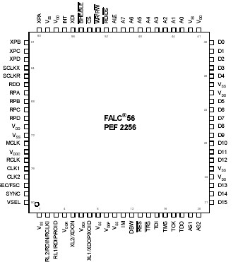
Pinout

  Connection Diagram


Specifications

Parameter
Symbol
Values
Unit
Note/Test
Condition
Min.
Typ.
Max.
Ambient temperature
under bias
TA
-40
+85
°C
Storage temperature
TSTG
-65
+125
°C
Moisture Level 3
temperature
TML3
+225
+245
°C
°C
According to IPS
J-STD 020
According to IFX
internal standard
Supply voltage (pads,
digital)
VDD
-0.5
3.30
4.50
V
-
Supply voltage (core,
digital)
VDDC
-0.5
1.80
2.40
V
-
Supply voltage (PLL,
analog)
VDDP
-0.5
3.30
4.50
V
-
Supply voltage
(receiver, analog)
VDDR
-0.5
3.30
4.50
V
-
Supply voltage
(transmitter, analog)
VDDX
-0.5
3.30
4.50
V
-
Receiver input signal
VRLmax
-0.8
4.50
V
RL1/RL2
Voltage on any pin
Vmax
-0.5
4.50
V
except VDDC,
RL1/RL2
ESD robustness CDM
V ESD,CDM
2000
V
1.5 kΩ, 100 pF;
according to EIA/
JESD22-A114-B
ESD robustness CDM
V ESD,CDM
500
V
According to
ESD Association
Standard
DS5.3.1 - 1999
Attention: If the 1.8 V power supply is externally driven on VDDC, the voltage on this pin must never exceed the 3.3 V supply voltages on pins VDD, VDDP, VDDX and VDDR, even during power up and power down of the circuit.

Attention: Absolute Maximum Ratings are stress ratings only, and functional operation and reliability under conditions beyond those defined in the normal operating conditions is not guaranteed. Stresses above the maximum ratings are likely to cause permanent damage to the chip.


Customers Who Bought This Item Also Bought

Margin,quality,low-cost products with low minimum orders. Secure your online payments with SeekIC Buyer Protection.
Line Protection, Backups
Motors, Solenoids, Driver Boards/Modules
Cables, Wires
Industrial Controls, Meters
Memory Cards, Modules
View more