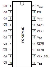
Features: · 100 ps device-to-device skew· 25 ps within device skew· 400 ps typical propagation delay· Maximum frequency > 2 GHz (typical)· Contains temperature compensation· PECL and HSTL mode: VCC = 2.375 V to 3.8 V with VEE = 0 V· NECL mode: VCC = 0 V with VEE = -2.375 V to -3.8 V· LVDS input...
PCKEP14: Features: · 100 ps device-to-device skew· 25 ps within device skew· 400 ps typical propagation delay· Maximum frequency > 2 GHz (typical)· Contains temperature compensation· PECL and HSTL mode: V...
SeekIC Buyer Protection PLUS - newly updated for 2013!
268 Transactions
All payment methods are secure and covered by SeekIC Buyer Protection PLUS.
Symbol |
Parameter |
Conditions |
Min |
Max |
Unit |
VCC |
PECL mode power supply |
VEE = 0 V |
- |
4.1 |
V |
VEE |
NECL mode power supply |
VCC = 0 V |
- |
-4.1 |
V |
VI |
PECL mode input voltage |
VEE = 0 V; VI VCC |
- |
4.1 |
V |
NECL mode input voltage |
VCC = 0 V; VI VEE |
- |
-4.1 |
V | |
Iout |
output current |
continuous |
- |
50 |
mA |
surge |
- |
100 |
mA | ||
IBB |
VBB source current |
0 |
0.1 |
mA | |
Tamb |
operating ambient temperature |
-40 |
+85 |
°C | |
Tstg |
storage temperature range |
-65 |
+150 |
°C | |
Rth(j-a) |
thermal resistance from junction to ambient |
0 LFPM |
- |
140 |
°C/W |
500 LFPM |
- |
100 |
°C/W | ||
Rth(j-c) |
thermal resistance from junction to case |
23 |
41 |
°C/W | |
Tsld |
soldering temperature |
- |
265 |
°C |
The PCKEP14 is a low skew 1-to-5 differential driver, designed with clock distribution in mind, accepting two clock sources into an input multiplexer. The ECL/PECL input signals can be either differential or single-ended (if the VBB output is used). HSTL inputs can be used when the PCKEP14 is operating under PECL conditions.
The PCKEP14 specifically guarantees low output-to-output skew. Optimal design,layout, and processing minimize skew within a device, and from device to device. To ensure that the tight skew specification is realized, both sides of any differential output need to be terminated identically into 50 resistors, even if only one output is being used. If an output pair is unused, both outputs may be left open (unterminated) without affecting skew.
The common enable (EN) of PCKEP14 is synchronous, outputs are enabled/disabled in the LOW state. This avoids a runt clock pulse when the device is enabled/disabled, as can happen with an asynchronous control. The internal flip-flop is clocked on the falling edge of the input clock, therefore, all associated specification limits are referenced to the negative edge of the clock input.
The PCKEP14, as with most other ECL devices, can be operated from a positive VCC supply in PECL mode. This allows the PCKEP14 to be used for high performance clock distribution in +3.3 V or +2.5 V systems.