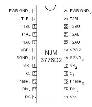
Features: • Suitable to drive any external MOS FET or bipolar power transistor
• Cross conduction prevented by time delay
• Digital filter on chip eliminates external filtering components
• Package DIP24ApplicationOutput current
The maximum peak output, sink/source, current is 500 mA. But due to the power handling capacity of the package this current can only be used for a short period of time (1mS). Recommended max continuous output current is 200 mA/output transistor. This is practical when driving MOS FET power transistors, since a high peak output current capability will rapidly charge/discharge the gate capacitance, while the continuous current usage is very small.
Current control
The regulated output current level to the motor winding is determined by the voltage at the reference input and the value of the sensing resistor, RS. The peak current through the sensing resistor (and the motor winding) can be expressed as: IM,peak = 0.1·VR / RS [A]
With a recommended value of 0.1 ohm for the sense resistor RS, a 5 V reference voltage will produce an output current of approximately 5 A. RS should be selected for maximum motor current. Chopping frequency, winding inductance and supply voltage also affect the current, but to much less extent.
For accurate current regulation, the sensing resistor should be a 0.5 - 1.5 W precision resistor, i. e. less than 1% tolerance and low temperature coefficient.
Recirculating diodes
Care must be taken to assure that the recirculating current from the motor winding has a free path at all times, when designing the external H-bridge otherwise may the voltage reach dangerous levels at the outputs. See figure 3. Make sure that there are recirculating diodes included in the transistors, or if not design in external diodes. Also make sure that these diodes are sufficient for the application i.e. regarding recovery time, voltage drop etc.
Pinout Specifications
| Parameter |
Pin no. [DIP] |
Symbol |
Min |
Max |
Unit |
| Voltage |
|
|
|
|
|
| Logic supply |
13 |
VCC |
0 |
7 |
V |
| Motor supply |
6, 19 |
VBB |
0 |
45 |
V |
| Logic inputs |
10, 11, 14, 15 |
VI |
-0.3 |
6 |
V |
| Analog inputs |
8, 9, 16, 17 |
VA |
-0.3 |
VCC |
V |
| Current |
|
|
|
|
|
| Output current t=1mS |
2, 3, 4, 5, 20, 21, 22, 23 |
IO |
-500 |
+500 |
mA |
| Logic inputs |
10, 11, 14, 15 |
II |
-10 |
- |
mA |
| Analog inputs |
8, 9, 16, 17 |
IA |
-10 |
- |
mA |
| Temperature |
|
|
|
|
|
| Junction temperature |
|
Tj |
- |
+150 |
°C |
| Storage temperature |
|
Tstg |
-55 |
+150 |
°C |
DescriptionThe NJM3776 is a switch-mode (chopper), constant-current controller intended for controlling external transistors in a high current stepper motor application. The NJM3776 has two channels, one for each winding of a two-phase stepper motor. The NJM3776 is equipped with a Disable input to simplify half stepping operation. The NJM3776 contains a clock oscillator, which is common for both driver channels, a set of comparators and flip-flops implementing the switching control, and two output sections each containing four outputs, two source and two sink, intended to drive an external Hbridge. Voltage supply requirements are +5 V for logic and +10 to +45 V for the outputs.

 NJM3776 Data Sheet


