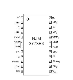
Features: • Dual chopper driver
• 750 mA continuous output current per channel
• High impedance current control inputs
• Digital filter on chip eliminates external filtering components
• Packages DIP22 / PLCC28 / EMP24(Batwing)ApplicationCurrent control
The regulated output current level to the motor winding is determined by the voltage at the reference input and the value of the sensing resistor, RS. The peak current through the sensing resistor (and the motor winding) can be expressed as: IM,peak = VR / RS [A]
With a recommended value of 0.5 ohm for the sensing resistor RS, a 0.25 V reference voltage will produce an output
current of approximately 500 mA. RS should be selected for maximum motor current. Be should not to exceed the absolute maximum output current which is 850 mA. Chopping frequency, winding inductance and supply voltage also affect the current, but to much less extent.
To improve noise immunity on the comparator inputs (VR and C), the control range may be increased to 0.5 V if RS is correspondingly changed to 1 ohm for a maximum output current of 500 mA.
For accurate current regulation, the sensing resistor should be a 0.5 - 1.0 W precision resistor, i. e. less than 1% tolerance and low temperature coefficient.
Pinout Specifications
| Parameter |
Pin no. [DIP] |
Symbol |
Min |
Max |
Unit |
| Voltage |
|
|
|
|
|
| Logic supply |
12 |
VCC |
0 |
7 |
V |
| Motor supply |
4, 19 |
VMM |
0 |
45 |
V |
| Logic inputs |
9, 10, 13, 14 |
VI |
-0.3 |
6 |
V |
| Analog inputs |
7, 8, 15, 16 |
VA |
-0.3 |
VCC |
V |
| Current |
|
|
|
|
|
| Motor output current |
1, 3, 20, 22 |
IM |
-850 |
+850 |
mA |
| Logic inputs |
9, 10, 13, 14 |
II |
-10 |
- |
mA |
| Analog inputs |
7, 8, 15, 16 |
IA |
-10 |
- |
mA |
| Temperature |
|
|
|
|
|
| Operating junction temperature |
|
Tj |
-40 |
+150 |
°C |
| Storage temperature |
|
Tstg |
-55 |
+150 |
°C |
| Power Dissipation (Package Data) |
|
|
|
|
|
| Power dissipation at TGND = +25°C, DIP and PLCC package |
|
PD |
- |
5 |
W |
| Power dissipation at TGND = +125°C, DIP package |
|
PD |
- |
2.2 |
W |
| Power dissipation at TGND = +125°C, PLCC package |
|
PD |
- |
2.6 |
W |
DescriptionThe NJM3773 is a switch-mode (chopper), constant-current driver with two channels: one for each winding of a two-phase stepper motor. The NJM3773 is also equipped with a Disable input to simplify half-stepping operation. The circuit is well suited for microstepping applications together with an external micro controller. The current control inputs are low current, high impedance inputs, which allows the use of unbuffered DAC or external high resistive resistor divider network. The NJM3773 contains a clock oscillator, which is common for both driver channels, a set of comparators and flip-flops implementing the switching control, and two output H-bridges, including recirculation diodes. Voltage supply requirements are +5 V for logic and +10 to +45 V for the motor. Maximum output current is 750mA per channel.

 NJM3773 Data Sheet


