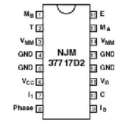
Features: • Half-step and full-step modes• Switched mode bipolar constant current drive• Wide range of current control 5 - 1200 mA• Wide voltage range 10 - 60 V• Thermal overload protection• Packages DIP16Application` Motor selection - Some stepper motors are no...
NJM37717: Features: • Half-step and full-step modes• Switched mode bipolar constant current drive• Wide range of current control 5 - 1200 mA• Wide voltage range 10 - 60 V• Therma...
SeekIC Buyer Protection PLUS - newly updated for 2013!
268 Transactions
All payment methods are secure and covered by SeekIC Buyer Protection PLUS.
` Motor selection
- Some stepper motors are not designed for continuous operation at maximum current. As the circuit drives a constant current through the motor, its temperature can increase, both at low- and high-speed operation. Some stepper motors have such high core losses that they are not suited for switched-mode operation.
` Interference
- As the circuit operates with switched-mode current regulation, interference-generation problems can arise in some applications. A good measure is then to decouple the circuit with a 0.1 µF ceramic capacitor, located near the package across the power line VMM and ground. Also make sure that the VR input is sufficiently decoupled. An electrolytic capacitor should be used in the +5 V rail, close to the circuit. The ground leads between RS, CC and circuit GND should be kept as short as possible. This applies also to the leads connecting RS and RC to pin 16 and pin 10 respectively. In order to minimize electromagnetic interference, it is recommended to route MA and MB leads in parallel on the printed circuit board directly to the terminal connector. The motor wires should be twisted in pairs, each phase separately, when installing the motor system.
` Unused inputs
- Unused inputs should be connected to proper voltage levels in order to obtain the highest possible noise immunity.
Parameter | Pin no. [DIP package] | Symbol | Min | Max | Unit |
Voltage | |||||
Logic supply | 6 | VCC | 0 | 7 | V |
Motor supply | 3, 14 | VMM | 0 | 60 | V |
Logic inputs | 7,8,9 | VI | -0.3 | 6 | V |
Comparator input | 10 | VC | -0.3 | VCC | V |
Reference input | 11 | VR | -0.3 | 15 | V |
Current | |||||
Motor output current | 1, 15 | IM | -1200 | +1200 | mA |
Logic inputs | 7,8,9 | II | -10 | - | mA |
Analog inputs | 10,11 | IA | -10 | - | mA |
Temperature | |||||
Operating junction temperature | Tj | -40 | +150 | °C | |
Storage temperature | Ts | -55 | +150 | °C |
NJM37717 is a stepper motor diver, which consists of a LS-TTL compatible logic input stage, a current sensor, a monostable multivibrator and a high power H-bridge output stage with built-in protection diodes.
NJM37717 is a high voltage version and pin compatible with NJM3717. The output current is up to 1200mA. Two of it and a small number of external components from a complete control and drive unit for stepper moter system.