Features: • Startup Circuit Eliminates the Need for Transformer Auxiliary Bias Winding
• Optional Auxiliary Bias Winding Override for Lowest Standby Power Applications
• Converter Output Overload and Open Loop Protection
• Auto Restart Fault Protection
• IC Thermal Fault Protection
• Unique, Dual Edge, Gated Oscillator Configuration for Extremely Fast Loop Response
• Oscillator Frequency Dithering with Controlled Slew Rate Driver for Reduced EMI
• Low Power Consumption Allowing European Blue Angel Compliance
• On−Chip 700 V Power Switch Circuit and Active Startup Circuit
• Rectified AC Line Source Operation from 85 V to 265 V
• Input Undervoltage Lockout with Hysteresis
• Oscillator Frequency Options of 44 kHz, 100 kHz, 136 kHz
Application• AC−DC Converters
• Wall Adapters
• Portable Electronic Chargers
• Low Power Standby and Keep−Alive SuppliesSpecifications
|
Rating |
Symbol |
Value |
Unit |
Power Switch and Startup Circuit
Drain Voltage Range
Drain Current Peak During Transformer Saturation |
VDS
IDS(pk) |
-0.3 to 700
2.0 Ilim Max |
V
A |
Power Supply/VCC Bypass and Control Input
Voltage Range
Current |
VIR
Imax |
-0.3 to 10
100 |
V
mA |
Thermal Characteristics
P Suffix, Plastic Package Case 626A−01
Junction−to−Lead
Junction−to−Air, 2.0 Oz. Printed Circuit Copper Clad
0.36 Sq. Inch
1.0 Sq. Inch
ST Suffix, Plastic Package Case 318E−04
Junction−to−Lead
Junction−to−Air, 2.0 Oz. Printed Circuit Copper Clad
0.36 Sq. Inch
1.0 Sq. Inch |
RJL
RJA
RJL
RJA |
9.0
77
60
14
74
55 |
°C/W |
| Operating Junction Temperature |
TJ |
-40 to +150 |
|
| Storage Temperature |
Tstg |
-65 to +150 |
|
1. Maximum Ratings are those values beyond which damage to the device may occur. Exposure to these conditions or conditions beyond those indicated may adversely affect device reliability. Functional operation under absolute maximum−rated conditions is not implied. Functional operation should be restricted to the Recommended Operating Conditions. A. This device series contains ESD protection and exceeds the following tests: Pins 1−3: Human Body Model 2000 V per MIL−STD−883, Method 3015. Machine Model Method 400 V. Pin 5: Human Body Model 1000 V per MIL−STD−883, Method 3015. Machine Model Method 400 V. Pin 5 is connected to the power switch and start−up circuits, and is rated only to the max voltage of the part, or 700 V.
B. This device contains Latch−up protection and exceeds �100 mA per JEDEC Standard JESD78.
DescriptionThe NCP1050 through NCP1055 are monolithic high voltage regulators that enable end product equipment to be compliant with low standby power requirements. This device series combines the required converter functions allowing a simple and economical power system solution for office automation, consumer, and industrial products.
These NCP1055 devices are designed to operate directly from a rectified AC line source. In flyback converter applications they are capable of providing an output power that ranges from 6.0 W to 40 W with a fixed AC input of 100 V, 115 V, or 230 V, and 3.0 W to 20 W with a variable AC input that ranges from 85 V to 265 V.
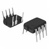
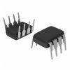
This NCP1055 device series features an active startup regulator circuit that eliminates the need for an auxiliary bias winding on the converter transformer, fault detector and a programmable timer for converter overload protection, unique gated oscillator configuration for extremely fast loop response with double pulse suppression, power switch current limiting, input undervoltage lockout with hysteresis, thermal shutdown, and auto restart fault detection. These NCP1055 devices are available in economical 8−pin dual−in−line and 4−pin SOT−223 packages.

 NCP1054 Data Sheet


