Features: • Typical Maximum Frequency > 2.0 GHz• 430 ps Typical Propagation Delay• Operating Range: VCC = 2.375 V to 3.8 V; VEE = -2.375 V to -5.5 V; GND = 0 V• Q Output will Default LOW with Inputs Open or at GNDPinout Specifications Symbol Parameter Condi...
NB100LVEP91: Features: • Typical Maximum Frequency > 2.0 GHz• 430 ps Typical Propagation Delay• Operating Range: VCC = 2.375 V to 3.8 V; VEE = -2.375 V to -5.5 V; GND = 0 V• Q Output w...
SeekIC Buyer Protection PLUS - newly updated for 2013!
268 Transactions
All payment methods are secure and covered by SeekIC Buyer Protection PLUS.
Symbol |
Parameter |
Condition 1 |
Condition 2 |
Rating |
Unit |
VCC |
PECL Power Supply |
GND = 0 V |
3.8 to 0 |
V | |
VEE |
NECL Power Supply |
GND = 0 V |
-5.5 to 0 |
V | |
VI |
PECL Input Voltage |
GND = 0 V GND = 0 V |
VI VCC VI VEE |
3.8 to 0 9.3 to 0 |
V V |
VOP |
Operating Voltage | ||||
Iout |
Output Current |
Continuous Surge |
50 100 |
mA mA | |
IBB |
PECL VBB Sink/Source |
±0.5 |
mA | ||
TA |
Operating Temperature Range |
−40 to +85 |
|||
Tstg |
Storage Temperature Range |
−65 to +150 |
|||
JA |
Thermal Resistance (Junction−to−Ambient) JEDEC 51−3 (1S − Single Layer Test Board) |
0 lfpm 500 lfpm |
20 SOIC 20 SOIC |
90 60 |
/W /W |
JA |
Thermal Resistance (Junction−to−Ambient) JEDEC 51−6 (2S2P−Multi Layer Test oard) with Filled Thermal Vias |
0 LFPM |
24 QFN |
47.3 |
/W |
JC |
Thermal Resistance (Junction−to−Case) |
std bd |
20 SOIC |
30 to 35 |
/W |
Tsol |
Wave Solder |
<2 to 3 sec @ 248 |
|
265 |
The NB100LVEP91 is a triple any level positive input to NECL output translator. The NB100LVEP91 accepts LVPECL, LVTTL, LVCMOS,HSTL, CML or LVDS signals, and translates them to differential NECL output signals (-2.5 V / -3.3 V / -5 V).
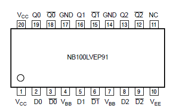
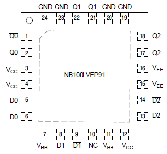
To accomplish the level translation the LVEP91 requires three power rails. The VCC supply should be connected to the positive supply, and the VEE pin should be connected to the negative power supply. The GND pins are connected to the system ground plane. Both VEE and VCC should be bypassed to ground via 0.01 F capacitors. Under open input conditions, the D input will be biased at VCC/2 and the D input will be pulled to GND. These conditions of NB100LVEP91 will force the Q outputs to a low, ensuring stability.
The VBB pin, an internally generated voltage supply, is available to NB100LVEP91 only. For single-ended input conditions, the unused differential input is connected to VBB as a switching reference voltage VBB may also rebias AC coupled inputs. When used, decouple VBB and VCC via a 0.01 F capacitor and limit current sourcing or sinking to 0.5 mA. When not used, VBB should be left open.