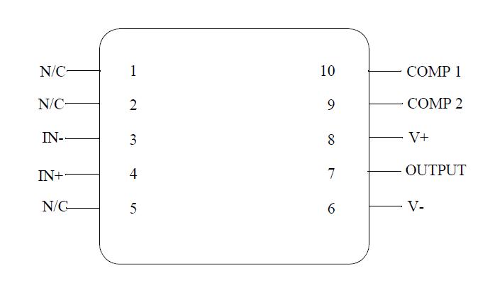
Pinout Specifications
Supply Voltage..........................................+22V
Power Dissipation(Note 2)
METAL CAN 330mW @ +125 C
CERDIP, 14 Lead ..................400mW @ +125 C
CERDIP, 8 Lead ....................400mW @ +125 C
CERPACK, 10 Lead ...............330mW @ +125 C
CERAMIC SOIC .....................330mW @ +125 C
Differential Input Current
(Note 3).................................................+10mA
Differential Input Voltage
(Note 5)....................................................+30V
Input Voltage
(Note 4)....................................................+20V
Output Short-Circuit Duration..........Continuous
Operating Temperature Range.-55 C to +125 C
Storage Temperature Range....-65 C to +150 C
Thermal Resistance
ThetaJA
METAL CAN (Still Air) ............................150 C/W
(500LF/Min Air flow) ...............................86 C/W
CERDIP, 14 Lead (Still Air)..................... 94 C/W
(500LF/Min Air flow) ...............................55 C/W
CERDIP, 8 Lead (Still Air) ......................120 C/W
(500LF/Min Air flow) ...............................68 C/W
CERPACK, 10 Lead (Still Air) .................225 C/W
(500LF/Min Air flow) ..............................142 C/W
CERAMIC SOIC (Still Air) .......................225 C/W
(500LF/Min Air Flow)............................. 142 C/W
ThetaJC
METAL CAN............................................. 38 C/W
CERDIP, 14 Lead ....................................13 C/W
CERDIP, 8 Lead ......................................17 C/W
CERPACK, 10 Lead .................................21 C/W
CERAMIC SOIC .......................................21 C/W
Package Weight
(Typical)
METAL CAN ..............................................990mg
CERDIP, 14 Lead ...................................2180mg
CERDIP, 8 Lead .....................................1090mg
CERPACK, 10 Lead ..................................255mg
CERAMIC SOIC........................................ 210mg
Maximum Junction Temperature................175 C
Soldering Information
(Soldering, 10 seconds) ............................300 C
ESD Tolerance
(Note 6)....................................................2000V
Note 1: Absolute Maximum Ratings indicate limits beyond which damage to the device may occur. Operating Ratings indicate conditions for which the device is functional, but do not guarantee specific performance limits. For guaranteed specifications and test conditions, see the Electrical Characteristics. The guaranteed specifications apply only for the test conditions listed. Some performance characteristics may degrade when the device is not operated under the listed test conditions.
Note 2: The maximum power dissipation must be derated at elevated temperatures and is dictated by Tjmax (maximum junction temperature), ThetaJA (package junction to ambient thermal resistance), and TA (ambient temperature). The maximum allowable power dissipation at any temperature is Pdmax = (Tjmax - TA) /ThetaJA or the number given in the Absolute Maximum Ratings, whichever is lower.
Note 3: The inputs are shunted with back-to-back diodes for overvoltage protection. Therefore, excessive current will flow if a differential input voltage in excess of 1V is applied between the inputs unless some limiting resistance is used.
Note 4: For supply voltages less than +20V, the absolute maximum input voltage is equal to the supply voltage.
Note 5: This rating is +1.0V unless resistances of 2K Ohms or greater are inserted in series with the inputs to limit current in the input shunt diodes to the maximum allowable value.
Note 6: Human body model, 1.5K Ohms in series with 100pF.
DescriptionThe LM108A is a precision operational amplifier having specifications a factor of ten better than FET amplifiers over a -55 C to +125 C temperature range.
MJLM108A-X operates with supply voltages from +2V to +20V and MJLM108A-X has sufficient supply rejection to use unregulated supplies. Although the circuit is interchangeable with and uses the same compensation as the LM101A, an alternate compensation scheme can be used to make it particularly insensitive to power supply noise and to make supply bypass capacitors unnecessary.
The low current error of the LM108A makes possible many designs that are not practical with conventional amplifiers. In fact, MJLM108A-X operates from 10M Ohms source resistances, introducing less error than MJLM108A-X like the 709 with 10K Ohms sources. Integrators with drifts less than 500 uV/sec and analog time delays in excess of one hour can be made using capacitors no larger than 1uF.

 MJLM108A-X Data Sheet


