|
Pin Number
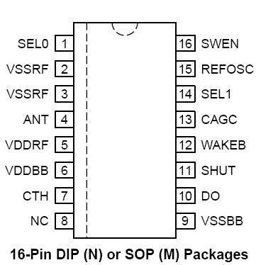
16-PinPkg. |
Pin Number
8-Pin Pkg. |
Pin Name
|
Pin Function |
|
1 |
|
SEL0 |
Bandwidth Selection Bit 0 (Input): Configure with SEL1 to set the desired
demodulator filter bandwidth. See Table 1. Internally pulled-up to VDDRF. |
|
2 |
1 |
VSSRF |
RF [Analog] Return (Input): Ground return to the RF section power supply.
See "Application Information" for bypass capacitor details. |
|
3 |
2 |
ANT |
Antenna (Input): High-impedance, internally ac coupled receiver input.
Connect this pin to the receive antenna. This FET gate input has approximately
2pF of shunt (parasitic) capacitance. See "Applications Information"
for optional band-pass filter information. |
|
5 |
3 |
VDDRF |
RF [Analog] Supply (Input): Positive supply input for the RF section of the
IC. VDDBB and VDDRF should be connected together directly at the IC
pins. Connect a low ESL, low ESR decoupling capacitor from this pin to
VSSRF, as short as possible. |
|
6 |
|
VDDBB |
Base-Band [Digital] Supply (Input): Positive supply input for the baseband
section of the IC. VDDBB and VDDRF should be connected together at the
IC pins. |
|
7 |
4 |
CTH |
[Data Slicing] Threshold Capacitor (External Component): Capacitor
extracts the dc average value from the demodulated waveform which
becomes the reference for the internal data slicing comparator. See "Applications
Information" for selection. |
|
8 |
|
NC |
not internally connected |
|
9 |
|
VSSBB |
Base-Band [Digital] Return (Input): Ground return to the baseband section
power supply. See "Application Information" for bypass capacitor and layout
details. |
|
10 |
5 |
DO |
Negative RF power output to drive one side of the transmit antenna. |
|
11 |
6 |
SHUT |
Shutdown (Input): Shutdown-mode logic-level control input. Pull low to
enable the receiver. This input has an internal pulled-up to VDDRF. |
|
12 |
|
WAKEB |
Wakeup (Output): Active-low output that indicates detection of an incoming
RF signal. Signal is determined by monitoring for data preamble. CMOSlevel
compatible. |
|
13 |
7 |
CAGC |
AGC Capacitor (External Component): Integrating capacitor for on-chip
AGC (automatic gain control). The decay/attack time-constant () ratio is
nominally 10:1. See "Applications Information" for capacitor selection. |
|
14 |
|
SEL1 |
Bandwidth Selection Bit 1 (Input): Configure with SEL0, programs to set the
desired demodulator filter bandwidth. See Table 1. Internally pulled-up to
VDDRF. |
|
15 |
8 |
REFOSC |
Reference Oscillator (External Component or Input): Timing reference for
on-chip tuning and alignment. Connect either a ceramic resonator or crystal
(mode dependent, see "Application Information"). between this pin and
VSSBB, or drive the input with an ac-coupled 0.5Vpp input clock. |
|
16 |
|
SWEN |
Sweep-Mode Enable (Input): Sweep- or fixed-mode operation control input.
When VSWEN is high, the MICRF004 is in sweep mode; when SWEN is
low, the receiver operates as a conventional single-conversion superheterodyne
receiver. This pin is internally pulled-up to VDDRF. |

 MICRF004 Data Sheet


