MC9S12DB128B

Features: • HCS12 Core 16-bit HCS12 CPUi. Upward compatible with M68HC11 instruction setii. Interrupt stacking and programmer's model identical to M68HC11iii.20-bit ALUiv. Instruction queuev. Enhanced indexed addressing MEBI (Multiplexed External Bus Interface) MMC (Module Mapping Control) I...

product image

MC9S12DB128B Picture
SeekIC No. : 004417410 Detail

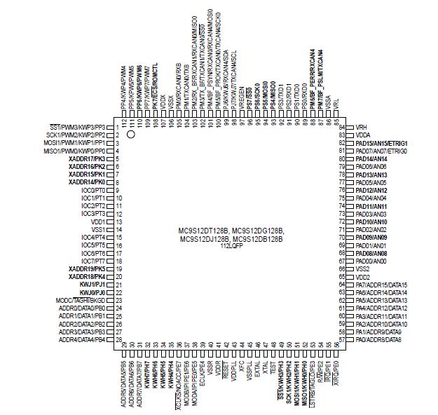
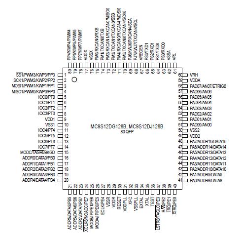
MC9S12DB128B: Features: • HCS12 Core 16-bit HCS12 CPUi. Upward compatible with M68HC11 instruction setii. Interrupt stacking and programmer's model identical to M68HC11iii.20-bit ALUiv. Instruction queuev. ...

floor Price/Ceiling Price

Part Number:
MC9S12DB128B
Supply Ability:
5000

Price Break

  • Qty
  • 1~5000
  • Unit Price
  • Negotiable
  • Processing time
  • 15 Days
Total Cost: $ 0.00

SeekIC Buyer Protection PLUS - newly updated for 2013!

  • Escrow Protection.
  • Guaranteed refunds.
  • Secure payments.
  • Learn more >>

Month Sales

268 Transactions

Rating

evaluate  (4.8 stars)

Upload time: 2024/5/22

Payment Methods

All payment methods are secure and covered by SeekIC Buyer Protection PLUS.

Notice: When you place an order, your payment is made to SeekIC and not to your seller. SeekIC only pays the seller after confirming you have received your order. We will also never share your payment details with your seller.
Product Details

Description


Features:

• HCS12 Core
16-bit HCS12 CPU
i. Upward compatible with M68HC11 instruction set
ii. Interrupt stacking and programmer's model identical to M68HC11
iii.20-bit ALU
iv. Instruction queue
v. Enhanced indexed addressing
MEBI (Multiplexed External Bus Interface)
MMC (Module Mapping Control)
INT (Interrupt control)
BKP (Breakpoints)
BDM (Background Debug Mode)
• CRG (Clock and Reset Generator)
Choice of low current Colpitts oscillator or standard Pierce Oscillator
PLL
COP watchdog
real time interrupt
clock monitor
• 8-bit and 4-bit ports with interrupt functionality
Digital filtering
Programmable rising or falling edge trigger
• Memory
128K Flash EEPROM
2K byte EEPROM
8K byte RAM
• Two 8-channel Analog-to-Digital Converters
10-bit resolution
External conversion trigger capability
• Three 1M bit per second, CAN 2.0 A, B software compatible modules
Five receive and three transmit buffers
Flexible identifier filter programmable as 2 x 32 bit, 4 x 16 bit or 8 x 8 bit
Four separate interrupt channels for Rx, Tx, error and wake-up
Low-pass filter wake-up function
Loop-back for self test operation
• Enhanced Capture Timer
16-bit main counter with 7-bit prescaler
8 programmable input capture or output compare channels
Two 8-bit or one 16-bit pulse accumulators
• 8 PWM channels
Programmable period and duty cycle
8-bit 8-channel or 16-bit 4-channel
Separate control for each pulse width and duty cycle
Center-aligned or left-aligned outputs
Programmable clock select logic with a wide range of frequencies
Fast emergency shutdown input
Usable as interrupt inputs
• Serial interfaces
Two asynchronous Serial Communications Interfaces (SCI)
Two Synchronous Serial Peripheral Interface (SPI)
Byteflight
• Byte Data Link Controller (BDLC)
• SAE J1850 Class B Data Communications Network Interface
Compatible and ISO Compatible for Low-Speed (<125 Kbps) Serial Data Communications in
Automotive Applications
• Inter-IC Bus (IIC)
Compatible with I2C Bus standard
Multi-master operation
Software programmable for one of 256 different serial clock frequencies
• 112-Pin LQFP and 80-Pin QFP package options
I/O lines with 5V input and drive capability
5V A/D converter inputs
Operation at 50MHz equivalent to 25MHz Bus Speed
Development support
Single-wire background debug™ mode (BDM)
On-chip hardware breakpoints


Pinout

  Connection Diagram  Connection Diagram


Specifications

Num Rating Symbol Min Max Unit
1

2

3

4

5

6

7

8

9

10


11


12


13
I/O, Regulator and Analog Supply Voltage

Digital Logic Supply Voltage 2

PLL Supply Voltage 2

Voltage difference VDDX to VDDR and VDDA

Voltage difference VSSX to VSSR and VSSA

Digital I/O Input Voltage

Analog Reference

XFC, EXTAL, XTAL inputs

TEST input

Instantaneous Maximum Current
Single pin limit for all digital I/O pins 3

Instantaneous Maximum Current
Single pin limit for XFC, EXTAL, XTAL4

Instantaneous Maximum Current
Single pin limit for TEST 5

Storage Temperature Range
VDD5

VDD

VDDPLL

DVDDX

DVSSX

VIN

VRH, VRL

VILV

VTEST


ID


IDL


IDT

Tstg
-0.3

-0.3

-0.3

-0.3

-0.3

-0.3

-0.3

-0.3

-0.3


-25


-25


-0.25

65
6.0

3.0

3.0

0.3

0.3

6.0

6.0

3.0

10.0


+25


+25


0

155
V

V

V

V

V

V

V

V

V

mA


mA


mA

°C


NOTES:
1. Beyond absolute maximum ratings device might be damaged.
2. The device contains an internal voltage regulator to generate the logic and PLL supply out of the I/O supply. The absolute maximum ratings apply when the device is powered from an external source.
3. All digital I/O pins are internally clamped to VSSX and VDDX, VSSR and VDDR or VSSA and VDDA.
4. Those pins are internally clamped to VSSPLL and VDDPLL.
5. This pin is clamped low to VSSPLL, but not clamped high. This pin must be tied low in applications.


Description

This section describes signals that connect off-chip. It includes a pinout diagram, a table of signal properties, and detailed discussion of signals. MC9S12DB128B is built from the signal description sections of the Block User Guides of the individual IP blocks on the device.


Customers Who Bought This Item Also Bought

Margin,quality,low-cost products with low minimum orders. Secure your online payments with SeekIC Buyer Protection.
Audio Products
Static Control, ESD, Clean Room Products
Computers, Office - Components, Accessories
Hardware, Fasteners, Accessories
Prototyping Products
DE1
View more