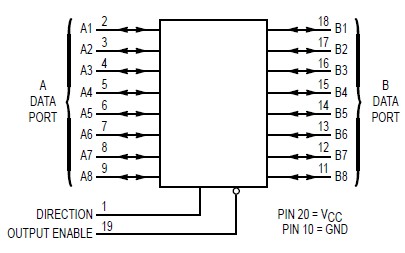
PinoutSpecifications Symbol Parameter Value Unit VCC DC Supply Voltage (Referenced to GND) 0.5 to + 7.0 V Vin DC Input Voltage (Referenced to GND) 0.5 to VCC + 0.5 V Vout DC Output Voltage (Referenced to GND) 0.5 to VCC + 0.5 V Iin ...
MC74HCT245A: PinoutSpecifications Symbol Parameter Value Unit VCC DC Supply Voltage (Referenced to GND) 0.5 to + 7.0 V Vin DC Input Voltage (Referenced to GND) 0.5 to V...
SeekIC Buyer Protection PLUS - newly updated for 2013!
268 Transactions
All payment methods are secure and covered by SeekIC Buyer Protection PLUS.
Features: Operating range: 38 to 47 Gb/s (min.) (note)Signal regeneration with full-rate clock sig...
Symbol |
Parameter |
Value |
Unit |
VCC |
DC Supply Voltage (Referenced to GND) |
0.5 to + 7.0 |
V |
Vin |
DC Input Voltage (Referenced to GND) |
0.5 to VCC + 0.5 |
V |
Vout |
DC Output Voltage (Referenced to GND) |
0.5 to VCC + 0.5 |
V |
Iin |
DC Input Current, per Pin |
± 20 |
mA |
Iout |
DC Output Current, per Pin |
± 35 |
mA |
ICC |
DC Supply Current, VCC and GND Pins |
± 75 |
mA |
PD |
Power Dissipation in Still Air, Plastic or Ceramic DIP† SOIC Package† SSOP or TSSOP Package† |
750 |
mW |
Tstg |
Storage Temperature |
65 to+150 |
°C |
TL |
Lead Temperature, 1 mm from Case for 10 Seconds (Plastic DIP, SOIC, SSOP or TSSOP Package) (Ceramic DIP) |
260 300 |
°C |
* Maximum Ratings are those values beyond which damage to the device may occur. Functional operation should be restricted to the Recommended Operating Conditions.
†Derating - Plastic DIP: 10 mW/°C from 65° to 125°C
Ceramic DIP: 10 mW/°C from 100 to 125°C
SOIC Package: 7 mW/°C from 65 to 125°C
SSOP or TSSOP Package: 6.1 mW/°C from 65 to 125°C
For high frequency or heavy load considerations, see Chapter 2 of the Motorola HighSpeed CMOS Data Book (DL129/D).
The MC54/74HCT245A is identical in pinout to the LS245. This device may be used as a level converter for interfacing TTL or NMOS outputs to High Speed CMOS inputs.
The MC54/74HCT245A is a 3state noninverting transceiver that is used for 2way asynchronous communication between data buses. The device has an activelow Output Enable pin, which is used to place the I/O ports into highimpedance states. The Direction control determines whether data flows from A to B or from B to A.
• Output Drive Capability: 15 LSTTL Loads
• TTL/NMOS Compatible Input Levels
• Outputs Directly Interface to CMOS, NMOS and TTL
• Operating Voltage Range: 4.5 to 5.5 V
• Low Input Current: 1.0 A
• In Compliance with the Requirements Defined by JEDEC Standard No. 7A
• Chip Complexity: 304 FETs or 76 Equivalent Gates