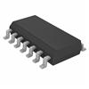
Features: • Output Drive Capability: 10 LSTTL Loads• Outputs Directly Interface to CMOS, NMOS, and TTL• Operating Voltage Range: 2 to 6 V• Low Input Current: 1 A• High Noise Immunity Characteristic of CMOS Devices• In Compliance with the Requirements Defined by ...
MC74HC259: Features: • Output Drive Capability: 10 LSTTL Loads• Outputs Directly Interface to CMOS, NMOS, and TTL• Operating Voltage Range: 2 to 6 V• Low Input Current: 1 A• High ...
SeekIC Buyer Protection PLUS - newly updated for 2013!
268 Transactions
All payment methods are secure and covered by SeekIC Buyer Protection PLUS.
Features: Operating range: 38 to 47 Gb/s (min.) (note)Signal regeneration with full-rate clock sig...
Symbol |
Parameter |
Value |
Unit |
VCC |
DC Supply Voltage (Referenced to GND) |
0.5 to +7.0 |
V |
Vin |
DC Input Voltage (Referenced to GND) |
1.5 to VCC +1.5 |
V |
Vout |
DC Output Voltage (Referenced to GND) |
0.5 to VCC + 0.5 |
V |
Iin |
DC Input Current, per Pin |
± 20 |
mA |
Iout |
DC Output Current, per Pin |
± 25 |
mA |
ICC |
DC Supply Current, VCC and GND Pins |
± 50 |
mA |
PD |
Power Dissipation in Still Air, Plastic or Ceramic DIP† SOIC Package† |
750 500 |
mW |
Tstg |
Storage Temperature |
65 to + 150 |
|
TL |
Lead Temperature, 1 mm from Case for 10 Seconds (Plastic DIP, SOIC or TSSOP Package) (Ceramic DIP) |
260 300 |
The MC54/74HC259 is identical in pinout to the LS259. The device inputs are compatible with standard CMOS outputs; with pullup resistors, they are compatible with LSTTL outputs.
The HC259 has four modes of operation as shown in the mode selection table. In the addressable latch mode, the data on Data In is written into the addressed latch. The addressed latch of MC74HC259 follows the data input with all nonaddressed latches remaining in their previous states. In the memory mode, all latches remain in their previous state and are unaffected by the Data or Address inputs. In the oneofeight decoding or demultiplexing mode, the addressed output of MC74HC259 follows the state of Data In with all other outputs in the LOW state. In the Reset mode all outputs are LOW and unaffected by the address and data inputs. When operating the HC259 as an addressable latch, changing more than one bit of the address could impose a transient wrong address. Therefore, this should only be done while in the memory mode.