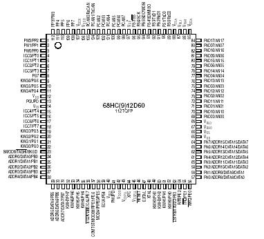
MC68HC912D60

Features: • 16-bit CPU12 Upward compatible with M68HC11 instruction set Interrupt stacking and programmer's model identical to M68HC11 20-bit ALU Instruction queue Enhanced indexed addressing• Multiplexed bus Single chip or expanded 16 address/16 data wide or 16 address/8 data narrow m...

product image

MC68HC912D60 Picture
SeekIC No. : 004416567 Detail

MC68HC912D60: Features: • 16-bit CPU12 Upward compatible with M68HC11 instruction set Interrupt stacking and programmer's model identical to M68HC11 20-bit ALU Instruction queue Enhanced indexed addressing&...

floor Price/Ceiling Price

Part Number:
MC68HC912D60
Supply Ability:
5000

Price Break

  • Qty
  • 1~5000
  • Unit Price
  • Negotiable
  • Processing time
  • 15 Days
Total Cost: $ 0.00

SeekIC Buyer Protection PLUS - newly updated for 2013!

  • Escrow Protection.
  • Guaranteed refunds.
  • Secure payments.
  • Learn more >>

Month Sales

268 Transactions

Rating

evaluate  (4.8 stars)

Upload time: 2024/11/27

Payment Methods

All payment methods are secure and covered by SeekIC Buyer Protection PLUS.

Notice: When you place an order, your payment is made to SeekIC and not to your seller. SeekIC only pays the seller after confirming you have received your order. We will also never share your payment details with your seller.
Product Details

Description


Features:

• 16-bit CPU12
Upward compatible with M68HC11 instruction set
Interrupt stacking and programmer's model identical to M68HC11
20-bit ALU
Instruction queue
Enhanced indexed addressing
• Multiplexed bus
Single chip or expanded
16 address/16 data wide or 16 address/8 data narrow mode
• Two 8-bit ports with key wake-up interrupt (2 pins only are available on 80QFP) and one I2C start bit detector    (112TQFP only)
• Memory
60K byte flash EEPROM, made of a 28K module and a 32K module with 8K bytes protected BOOT section in each        module (68HC912D60)
60K byte ROM (68HC12D60)
1K byte EEPROM
2K byte RAM
• Analog-to-digital converters
2 x 8-channels, 10-bit resolution in 112TQFP
1 x 8-channels, 8-bit resolution in 80QFP
• 1M bit per second, CAN 2.0 A, B software compatible module
Two receive and three transmit buffers
Flexible identifier filter programmable as 2 x 32 bit, 4 x 16 bit or 8 x 8 bit
Four separate interrupt channels for Rx, Tx, error and wake-up
Low-pass filter wake-up function
In 80QFP, only TxCAN and RxCAN pins are available
Loop-back for self test operation
Programmable link to a timer input capture channel, for timestamping and network synchronization.
• Enhanced capture timer (ECT)
16-bit main counter with 7-bit prescaler
8 programmable input capture or output compare channels; of the 8 input captures with buffer
Input capture filters and buffers, three successive captures on four channels, or two captures on four channels     with a capture/compare selectable on the remaining four
Four 8-bit or two 16-bit pulse accumulators
16-bit modulus down-counter with 4-bit prescaler
Four user-selectable delay counters for signal filtering
• 4 PWM channels with programmable period and duty cycle
8-bit 4-channel or 16-bit 2-channel
Separate control for each pulse width and duty cycle
Center- or left-aligned outputs
Programmable clock select logic with a wide range of frequencies
• Serial interfaces
Two asynchronous serial communications interfaces (SCI)
MI-Bus implemented on final devices
Synchronous serial peripheral interface (SPI)
• LIM (light integration module)
WCR (windowed COP watchdog, real time interrupt, clock monitor)
ROC (reset and clocks)
MEBI (multiplexed external bus interface)
MBI (internal bus interface and map)
INT (interrupt control)
• Clock generation
Phase-locked loop clock frequency multiplier
Limp home mode in absence of external clock
Slow mode divider
Low power 0.5 to 16 MHz crystal oscillator reference clock
• 112-Pin TQFP package or 80-pin QFP package
Up to 68 general-purpose I/O lines, plus up to 18 input-only lines in 112TQFP or Up to 48 general-purpose I/O     lines, plus up to 10 input-only lines in 80QFP
• 8MHz operation at 5V
• Development support
Single-wire background debug™ mode (BDM)
On-chip hardware breakpoints


Pinout

  Connection Diagram


Specifications

Rating
Symbol
Value
Unit
Supply voltage
VDD, VDDA, VDDX, VDDPLL
−0.3 to +6.5
V
Input voltage
VIN
−0.3 to +6.5
V
Operating temperature range
68HC(9)12D60PV8
68HC(9)12D60CPV8
68HC(9)12D60VPV8
68HC(9)12D60MPV8 (single chip mode only)
TA
TL to TH
0 to +70
−40 to +85
40 to +105
40 to +125
°C
Operating temperature range
68HC(9)12D60FU8
68HC(9)12D60CFU8
68HC(9)12D60VFU8
68HC(9)12D60MFU8 (single chip mode only)
TA
TL to TH
0 to +70
−40 to +85
40 to +105
40 to +125
°C
Storage temperature range
Tstg
−55 to +150
°C
Current drain per pin(2)
Excluding VDD and VSS
IIN
±25
mA
VDD differential voltage
VDD−VDDX
6.5
V


Customers Who Bought This Item Also Bought

Margin,quality,low-cost products with low minimum orders. Secure your online payments with SeekIC Buyer Protection.
Cables, Wires - Management
Circuit Protection
Line Protection, Backups
Connectors, Interconnects
Transformers
View more