MC68HC08AS32A

Features: Features of the MC68HC08AS32A include:• High-performance M68HC08 architecture• Fully upward-compatible object code with M6805, M146805, and M68HC05 Families• 8.4-MHz internal bus frequency• 32,256 bytes of read-only memory (ROM)• ROM data security• 512...

product image

MC68HC08AS32A Picture
SeekIC No. : 004416382 Detail

MC68HC08AS32A: Features: Features of the MC68HC08AS32A include:• High-performance M68HC08 architecture• Fully upward-compatible object code with M6805, M146805, and M68HC05 Families• 8.4-MHz inte...

floor Price/Ceiling Price

Part Number:
MC68HC08AS32A
Supply Ability:
5000

Price Break

  • Qty
  • 1~5000
  • Unit Price
  • Negotiable
  • Processing time
  • 15 Days
Total Cost: $ 0.00

SeekIC Buyer Protection PLUS - newly updated for 2013!

  • Escrow Protection.
  • Guaranteed refunds.
  • Secure payments.
  • Learn more >>

Month Sales

268 Transactions

Rating

evaluate  (4.8 stars)

Upload time: 2024/11/27

Payment Methods

All payment methods are secure and covered by SeekIC Buyer Protection PLUS.

Notice: When you place an order, your payment is made to SeekIC and not to your seller. SeekIC only pays the seller after confirming you have received your order. We will also never share your payment details with your seller.
Product Details

Description


Features:

Features of the MC68HC08AS32A include:
• High-performance M68HC08 architecture
• Fully upward-compatible object code with M6805, M146805, and M68HC05 Families
• 8.4-MHz internal bus frequency
• 32,256 bytes of read-only memory (ROM)
• ROM data security
• 512 bytes of on-chip electrically erasable programmable read-only memory (EEPROM)
• 1024 bytes of on-chip random-access memory (RAM)
• Serial peripheral interface module (SPI)
• Serial communications interface module (SCI)
• 16-bit, 6-channel timer interface module (TIM)
• Clock generator module (CGM)
• 8-bit, 15-channel analog-to-digital converter module (ADC)
• SAE J1850 byte data link controller digital module (BDLC-D)
• System protection features:
   Computer operating properly (COP) with optional reset
   Low-voltage detection with optional reset
   Illegal opcode detection with optional reset
   Illegal address detection with optional reset
• Low-power design (fully static with stop and wait modes)
• Master reset pin and power-on reset
Features of the CPU08 include:
• Enhanced HC05 programming model
• Extensive loop control functions
• 16 addressing modes (eight more than the HC05)
• 16-bit index register and stack pointer
• Memory-to-memory data transfers
• Fast 8 * 8 multiply instruction
• Fast 16/8 divide instruction
• Binary-coded decimal (BCD) instructions
• Optimization for controller applications
• C language support


Application

Please deliver the application program to Motorola in one of these:
• Macintosh®(1) 3 1/2-inch diskette (double-sided 800 K or double-sided high-density 1.4 M)
• MS-DOS®(2) or PC-DOSTM(3) 3 1/2-inch diskette (double-sided 720 K or double-sided high-density 1.44 M)
• MS-DOS® or PC-DOSTM 5 1/4-inch diskette (double-sided double-density 360 K or double-sided high-density 1.2 M)
   Use positive logic for data and addresses.When submitting the application program on a diskette, clearly label the
diskette with this information:
• Customer name
• Customer part number
• Project or product name
• File name of object code
• Date
• Name of operating system that formatted diskette
• Formatted capacity of diskette


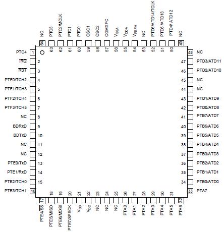
Pinout

  Connection Diagram


Specifications

Maximum ratings are the extreme limits to which the MCU can be exposed without permanently damaging it.

The MCU contains circuitry to protect the inputs against damage from high static voltages; however, do not apply voltages higher than those shown in the table below. Keep VIN and VOUT within the range VSS (VIN or VOUT) VDD. Connect unused inputs to the appropriate voltage level, either VSS or VDD.

Rating
Symbol
Value
Unit
Supply voltage
VDD
0.3 to +6.0
V
Input voltage
VIn
VSS 0.3
to VDD +0.3
V
Maximum current per pin
excluding VDD and VSS
I
±25
mA
Storage temperature
TSTG
55 to +150
°C
Maximum current out of VSS
IMVSS
100
mA
Maximum current into VDD
IMVDD
100
mA
Reset IRQ input voltage
VHI
VDD to VDD + 2
°C
Operating temperature range
TA
-40to125
°C
Operating voltage range
VDD
5.0 ± 10%
V
Thermal resistance
PLCC (52 pins)
QFP (64 pins)
JA
50
70
°C/W
I/O pin power dissipation
PI/O
User determined
W
Power dissipation(1)
PD
PD = (IDD x VDD) +
PI/O = K/(TJ + 273°C)
W
Constant(2)
K
PD x (TA + 273°C)
+ (PD 2 x JA)
W/°C
Average junction temperature
TJ
TA = PD * JA
°C
Maximum junction temperature
TJM
150
°C
1. Power dissipation is a function of temperature
2. K is a constant unique to the device. K can be determined from a known TA and measured PD. With this value of K, PD and TJ can be determined for any value of TA.


Customers Who Bought This Item Also Bought

Margin,quality,low-cost products with low minimum orders. Secure your online payments with SeekIC Buyer Protection.
Optoelectronics
Prototyping Products
DE1
Resistors
Integrated Circuits (ICs)
Power Supplies - External/Internal (Off-Board)
Discrete Semiconductor Products
View more