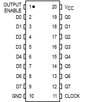
Features: • Output Drive Capability: 15 LSTTL Loads• TTL NMOS Compatible Input Levels• Outputs Directly Interface to CMOS, NMOS and TTL• Operating Voltage Range: 4.5 to 5.5 V• Low Input Current: 1.0 mA• In Compliance with the Requirements Defined by JEDEC Standa...
MC54HCT574A: Features: • Output Drive Capability: 15 LSTTL Loads• TTL NMOS Compatible Input Levels• Outputs Directly Interface to CMOS, NMOS and TTL• Operating Voltage Range: 4.5 to 5.5 V...
SeekIC Buyer Protection PLUS - newly updated for 2013!
268 Transactions
All payment methods are secure and covered by SeekIC Buyer Protection PLUS.
PinoutDescriptionThe F373 contains eight D-type latches with 3-state output buffers. When the Latc...
PinoutDescriptionThe F374 consists of eight edge-triggered flip-flops with individual D-type input...
Symbol | Parameter | Value | Unit |
vcc | DC Supply Voltage (Referenced to GND) | 0.5 to +7.0 | V |
VIN | DC Input Voltage (Referenced to GND) | 0.5 to VCC + 0.5 | V |
VOUT | DC Output Voltage (Referenced to GND) | 0.5 to VCC + 0.5 | V |
LIN | DC Input Current, per Pin | ±20 | mA |
IOUT | DC Onput Current, per Pin | ±35 | mA |
ICC | DC Supply Current Per Supply Pin | ±75 | mA |
PD | Power dissipation in still air piastic DIP SOIC package |
750 500 |
mW |
TSTG | Storage Temperature | 65 to +150 | °C |
TL | Lead Temperature, 1 mm from Case for 10 Seconds (Plastic DIP or SOIC Package) |
260 | °C |
*Maximum Ratings are those values beyond which damage to the device may occur.
Functional operation should be restricted to the Recommended Operating Conditions.
†Derating - Plastic DIP: 10 mW/C from 65 to 125C
SOIC Package: 7 mW/C from 65 to 125C
For high frequency or heavy load considerations, see Chapter 2 of the Motorola HighSpeed CMOS Data Book (DL129/D).
The MC54/74HCT574A is identical in pinout to the LS574. This device may be used as a level converter for interfacing TTL or NMOS outputs to High Speed CMOS inputs.
Data meeting the setup time is clocked to the outputs with the rising edge of the Clock. The Output Enable input of MC54HCT574A does not affect the states of the flipflops, but when Output Enable is high, all device outputs are forced to the highimpedance state. Thus, data may be stored even when the outputs are not enabled.
The HCT574A is identical in function to the HCT374A but has the flipflop inputs on the opposite side of the package from the outputs to facilitate PC board layout.