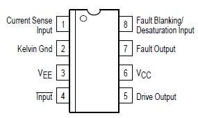
Pinout Specifications
| Rating |
Symbol |
Value |
Unit |
Power Supply Voltage
VCC to VEE
Kelvin Ground to VEE (Note 1) |
VCC VEE
KGnd VEE |
20
20 |
V |
| Logic Input |
Vin |
VEE 0.3 to VCC |
V |
| Current Sense Input |
VS |
0.3 to VCC |
V |
| Blanking/Desaturation Input |
VBD |
0.3 to VCC |
V |
Gate Drive Output
Source Current
Sink Current
Diode Clamp Current |
IO |
1.0
2.0
1.0 |
A |
Fault Output
Source Current
Sink Curent |
IFO |
25
10 |
mA |
Power Dissipation and Thermal Characteristics
D Suffix SO8 Package, Case 751
Maximum Power Dissipation @ TA = 50
Thermal Resistance, JunctiontoAir
P Suffix DIP8 Package, Case 626
Maximum Power Dissipation @ TA = 50
Thermal Resistance, JunctiontoAir |
PD
RJA
PD
RJA |
0.56
180
1.0
100 |
W
/W
W
/W |
| Operating Junction Temperature |
TJ |
+150 |
|
| Operating Ambient Temperature |
TA |
40 to +105 |
|
| Storage Temperature Range0 |
Tstg |
65 to +150 |
|
NOTE: ESD data available upon request.DescriptionThe MC33153 is specifically designed as an IGBT driver for high power applications that include ac induction motor control, brushless dc motor control and uninterruptable power supplies. Although designed for driving discrete and module IGBTs, this device offers a cost effective solution for driving power MOSFETs and Bipolar Transistors. MC33153 protection features include the choice of desaturation or overcurrent sensing and undervoltage detection. These devices are available in dualinline and surface mount packages and include the following features:
• High Current Output Stage: 1.0 A Source/2.0 A Sink
• Protection Circuits for Both Conventional and Sense IGBTs
• Programmable Fault Blanking Time
• Protection against Overcurrent and Short Circuit
• Undervoltage Lockout Optimized for IGBT's
• Negative Gate Drive Capability
• Cost Effectively Drives Power MOSFETs and Bipolar Transistors
The MC33153 has the following features including (1)High Current Output Stage: 1.0 A Source/2.0 A Sink;(2)Protection Circuits for Both Conventional and Sense IGBTs;(3)Programmable Fault Blanking Time;(4)Protection against Overcurrent and Short Circuit;(5)Undervoltage Lockout Optimized for IGBT's;(6)Cost Effectively Drives Power MOSFETs and Bipolar Transistors.
The MC33153 is specifically designed as an IGBT driver for high power applications that include ac induction motor control, brushless do motor control and uninterruptable power supplies. Although designed for driving discrete and module IGBTs, this device offers a cost effective solution for driving power MOSFETs and BipolarTransistors. Device protection features include the choice of desaturation or overcurrent sensing and undervoltage detection. The most important design aspect of an IGBT gate drive is optimization of the switching characteristics. The switching characteristics are especially important in motor control applications in which PWM transistors are used in a bridge configuration. In these applications, the gate drive circuit components should be selected to optimize turn-on, turn-off and off-state impedance.
The MC33153 has an active high fault output. The fault output may be easily interfaced to an optoisolator. While it is important that all faults are properly reported, it is equally important that no false signals are propagated. Again, a high dv/dt optoisolator should be used.The LED drive provides a resistor programmable current of 10 to 20 mA when on, and provides a low impedance path when off. An active high output, resistor, and small signal diode provide an excellent LED driver. It is desirable to protect an IGBT from insufficient gate voltage. IGBTs require 15 V on the gate to achieve the rated on-voltage. At gate voltages below 13 V, the on-voltage increases dramatically, especially at higher currents. At very low gate voltages, below 10 V, the IGBT may operate in the linear region and quickly overheat. Many PWM motor drives use a bootstrap supply for the upper gate drive. The UVLO provides protection for the IGBT in case the bootstrap capacitor discharges.

 MC33153 Data Sheet


