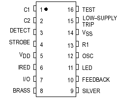
Features: • Complies with the UL217 and UL268 Specifications
• Operating Voltage Range: 6 to 12 V
• Operating Temperature Range: 10 to 60
• Average Supply Current: 8 A
• I/O Pin Allows Units to be Interconnected for Common Signalling
• PowerOn Reset Places IC in Standby Mode (NonAlarm State)
• Electrostatic Discharge (ESD) and Latch Up Protection Circuitry on All Pins
• Chip Complexity: 2000 FETs, 12 NPNs, 16 Resistors, and 10 Capacitors
• Supports NFPA 72, ANSI S3.41, and ISO 8201 Audible Emergency Evacuation SignalsPinout Specifications
|
Symbol |
Characteristic |
Value |
Unit |
|
VDD |
DC Supply Voltage |
0.5 to 12.0 |
V |
|
Vin |
DC Input Voltage C1, C2, Detect
OSC, LowSupply Trip
I/O
Feedback
Test |
0.25 to VDD + 0.25
0.25 to VDD + 0.25
0.25 to VDD + 10
15 to + 25
1.0 to VDD + 0.25 |
V |
|
Iin |
DC Input Current, per Pin |
± 10 |
mA |
|
Iout |
DC Output Current, per Pin |
± 25 |
mA |
|
IDD |
DC Supply Current, VDD and VSS Pins |
+ 25/ 150 |
mA |
|
PD |
Power Dissipation in Still Air, 5 Seconds
Continuous |
1200**
350*** |
mW |
|
Tstg |
Storage Temperature |
65 to + 150 |
|
|
TL |
Lead Temperature, 1 mm from Case for 10 Seconds |
260 |
|
*Maximum Ratings are those values beyond which damage to the device may occur. Functional operation should
be restricted to the limits in the Electrical Characteristics tables.
** Derating: 12 mW/ from 25° to 60.
*** Derating: 3.5 mW/ from 25° to 60.
This device contains protection circuitry to guard against damage due to high static voltages or electric fields. However, precautions must be taken to avoid applications of any voltage higher than maximum rated voltages
to this highimpedance circuit. For proper operation, V
in and V
out should be constrained to the range V
SS (V
in or V
out) V
DD except for the I/O, which can exceed V
DD, and the Test input, which can go below V
SS.
Unused inputs must always be tied to an appropriate logic voltage level (e.g., either V
SS or V
DD). Unused outputs and/or an unused I/O must be left open.
DescriptionThe CMOS MC145012 is an advanced smoke detector component containing sophisticated verylowpower analog and digital circuitry. The MC145012 is used with an infrared photoelectric chamber. Detection is accomplished by sensing scattered light from minute smoke particles or other aerosols. When detection occurs, a pulsating alarm is sounded via onchip pushpull drivers and an external piezoelectric transducer.
The variablegain photo amplifier allows direct interface to IR detectors (photodiodes). Two external capacitors, C1 and C2, C1 being the larger, determine the gain settings. Low gain is selected by the MC145012 during most of the standby state. Medium gain is selected during a localsmoke condition. High gain of MC145012 is used during pushbutton test. During standby, the special monitor circuit which periodically checks for degraded chamber sensitivity uses high gain also.
The I/O pin, in combination with VSS, can be used to interconnect up to 40 units for common signaling. An onchip current sink provides noise immunity when the I/O is an input. A localsmoke condition activates the shortcircuitprotected I/O driver, thereby signaling remote smoke to the interconnected units. Additionally, the I/O pin can be used to activate escape lights, enable auxiliary or remote alarms, and/or initiate autodialers.
While in standby, the lowsupply detection circuitry conducts periodic checks using a pulsed load current from the LED pin. The trip point is set using two external resistors. The supply for the MC145012 can be a 9 V battery.
A visible LED flash accompanying a pulsating audible alarm indicates a localsmoke condition. A pulsating audible alarm with no LED flash indicates a remotesmoke condition. A beep or chirp occurring virtually simultaneously with an LED flash indicates a lowsupply condition. A beep or chirp occurring halfway between LED flashes indicates degraded chamber sensitivity. A lowsupply condition does not affect the smoke detection capability if VDD 6 V. Therefore, the lowsupply condition and degraded chamber sensitivity can be further distinguished by performing a pushbutton (chamber) test.

 MC145012 Data Sheet


