MC10EP195

Features: ••Programmable Range: 0 ns to 10 ns•Delay Range: 2.2 ns to 12.2 ns•10 ps Increments•PECL Mode Operating Range:VCC= 3.0 V to 3.6 V with VEE= 0 V•NECL Mode Operating Range: VCC= 0 V with VEE= −3.0 V to −3.6 V••Safety Clamp on Inpu...

product image

MC10EP195 Picture
SeekIC No. : 004415031 Detail

MC10EP195: Features: ••Programmable Range: 0 ns to 10 ns•Delay Range: 2.2 ns to 12.2 ns•10 ps Increments•PECL Mode Operating Range:VCC= 3.0 V to 3.6 V with VEE= 0 V•NECL Mod...

floor Price/Ceiling Price

Part Number:
MC10EP195
Supply Ability:
5000

Price Break

  • Qty
  • 1~5000
  • Unit Price
  • Negotiable
  • Processing time
  • 15 Days
Total Cost: $ 0.00

SeekIC Buyer Protection PLUS - newly updated for 2013!

  • Escrow Protection.
  • Guaranteed refunds.
  • Secure payments.
  • Learn more >>

Month Sales

268 Transactions

Rating

evaluate  (4.8 stars)

Upload time: 2024/11/27

Payment Methods

All payment methods are secure and covered by SeekIC Buyer Protection PLUS.

Notice: When you place an order, your payment is made to SeekIC and not to your seller. SeekIC only pays the seller after confirming you have received your order. We will also never share your payment details with your seller.
Product Details

Description


Features:


•Programmable Range: 0 ns to 10 ns
•Delay Range: 2.2 ns to 12.2 ns
•10 ps Increments
•PECL Mode Operating Range:VCC= 3.0 V to 3.6 V with VEE= 0 V
•NECL Mode Operating Range: VCC = 0 V with VEE= −3.0 V to −3.6 V

•Safety Clamp on Inputs
•A Logic High on the EN Pin Will Force Q to LogicLow
•D[10:0] Can Accept Either ECL, LVCMOS, or LVTTLInputs
•VBBOutput Reference Voltage


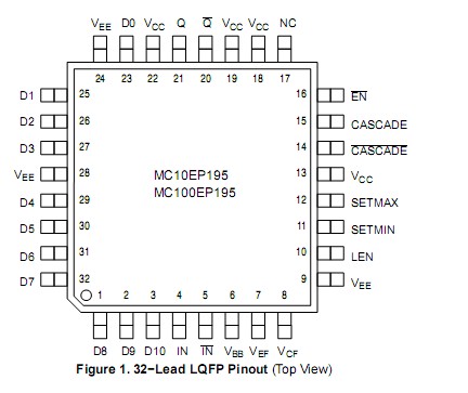
Pinout

  Connection Diagram


Specifications

Symbol


Parameter

Condition 1

Condition 2

Rating

Unit
VCC PECL Mode Power Supply VEE= 0 V   6 V
VEE NECL Mode Power Supply VCC= 0 V   -6 V
VI PECL Mode Input Voltage
NECL Mode Input Voltage
VEE= 0 V
VCC= 0 V

VIVCC

VIVEE

6
-6
V
V
IOUT Output Current Continuous
Surge
  50
100
mA
mA
IBB VBBSink/Source     ±0.5 mA
TA Operating Temperature Range     -40 to +85
Tstg Storage Temperature Range     -65 to+150
0JA Thermal Resistance (Junction-to-Ambient) 0 LFPM
500 LFPM
LQFP−23
LQFP−23
80
55
/W
/W
0JC Thermal Resistance (Junction-to-Case) std bd LQFP−23 12 to 17 /W
Tsol Wave Solder < 2 to 3sec@248°C   265


Description

The MC10/100EP195 is a Programmable Delay Chip (PDC) designed primarily for clock deskewing and timing adjustment. It provides variable delay of a differential NECL/PECL input transition.

The delay section MC10/100EP195 consists of a programmable matrix of gates and multiplexers as shown in the logic diagram, Figure 2. The delay increment of the EP195 has a digitally selectable resolution of about 10 ps and a net range of up to 10.2 ns. The required delay is selected by the 10 data select inputs D[9:0] values and controlled by the LEN (pin 10). A LOW level on LEN allows a transparent LOAD mode of real time delay values by D[9:0]. A LOW to HIGH transition on LEN will LOCK and HOLD current values present against any subsequent changes in D[10:0]. The approximate delay values of MC10/100EP195 for varying tap numbers correlating to D0 (LSB) through D9 (MSB) are shown in Table 6 and Figure 3.

Because the MC10/100EP195 is designed using a chain of multiplexers it has a fixed minimum delay of 2.2 ns. An additional pin D10 is provided for controlling Pins 14 and 15, CASCADE and CASCADE, also latched by LEN, in cascading multiple PDCs for increased programmable range. The cascade logic allows full control of multiple PDCs. Switching devices from all "1" states on D[0:9] with SETMAX LOW to all "0" states on D[0:9] with SETMAX HIGH will increase the delay equivalent to "D0", the minimum increment. Select input pins D[10:0] may be threshold controlled of MC10/100EP195 by combinations of interconnects between VEF(pin 7) and VCF(pin 8) for LVCMOS, ECL, or LVTTL level signals. For LVCMOS input levels, leave VCFand VEFopen. For ECL operation, short VCF andVEF(pins 7 and 8). For LVTTL level operation, connect a 1.5 V supply reference to VCFand leave open VEFpin. The 1.5 V reference voltage to VCFpin can be accomplished by placing a 2.2 


Customers Who Bought This Item Also Bought

Margin,quality,low-cost products with low minimum orders. Secure your online payments with SeekIC Buyer Protection.
Industrial Controls, Meters
Sensors, Transducers
Boxes, Enclosures, Racks
Undefined Category
Discrete Semiconductor Products
LED Products
View more