Features: • 1.1 ns Typical Propagation Delay• Maximum Frequency > 275 MHz Typical• Operating Range: VCC = 3.0 V to 3.6 V;VEE = −5.5 V to −3.0 V; GND = 0 V• 24 mA TTL Outputs• Q Output Will Default LOW with Inputs Open or at VEE• VBB Output• ...
MC100EPT25: Features: • 1.1 ns Typical Propagation Delay• Maximum Frequency > 275 MHz Typical• Operating Range: VCC = 3.0 V to 3.6 V;VEE = −5.5 V to −3.0 V; GND = 0 V• 24 ...
SeekIC Buyer Protection PLUS - newly updated for 2013!
268 Transactions
All payment methods are secure and covered by SeekIC Buyer Protection PLUS.
US $4.26 - 6.3 / Piece
Counter Shift Registers 5V ECL 8-Bit Binary Up Synchronous
• 1.1 ns Typical Propagation Delay
• Maximum Frequency > 275 MHz Typical
• Operating Range: VCC = 3.0 V to 3.6 V;
VEE = −5.5 V to −3.0 V; GND = 0 V
• 24 mA TTL Outputs
• Q Output Will Default LOW with Inputs Open or at VEE
• VBB Output
• Open Input Default State
• Safety Clamp on Inputs
• Pb−Free Packages are Available
Symbol | Parameter | Condition 1 | Condition2 | Rating | Units |
VCC | Core Power Supply | GND = 0 V | VCCO = -0.5 V | 3.8 | V |
VCCO | HSTL Output Power Supply | GND = 0 V | VCC = 3.3 V | -6 | V |
VIN | Input Voltage | GND = 0 V | 0 to VEE | V | |
IBB | VBB Sink/Source | ± 0.5 | mA | ||
TA | Operating Temperature Range | −40 to +85 | °C | ||
Tstg | Storage Temperature Range | -65 to +150 | °C | ||
JA | Thermal Resistance (Junction−to−Ambient) | 0 LFPM 500 LFPM |
8 SOIC 8 SOIC |
190 130 |
°C/W °C/W |
JC | Thermal Resistance (Junction−to−Case) | std bd | 8 SOIC | 41 to 44 | °C/W °C/W |
Tsol | Wave Solder | < 2 to 3 sec @ 248°C | 265 | °C |
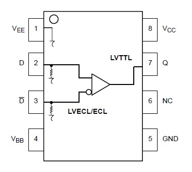
The MC100EPT25 is a Differential ECL to LVTTL translator. This device requires +3.3 V, −3.3 V to −5.2 V, and ground. The small outline 8−lead package and the single gate of the EPT25 make it ideal for applications which require the translation of a clock or data signal.
The VBB output allows the MC100EPT25 to also be used in a single−ended input mode. In this mode the VBB output is tied to the D input for a inverting buffer or the D input for a non−inverting buffer. If used, the VBB pin should be bypassed to ground with at least a 0.01 F capacitor.