Features: ±40V Fault Protection with Power Off ±36V Fault Protection with ±15V Supplies
All Switches Off with Power Off
Rail-to-Rail Signal Handling
Output Clamped to Appropriate Supply Voltage During Fault Condition; No Transition Glitch
175½ max Signal Paths with ±15V Supplies
No Power-Supply Sequencing Required
±4.5V to ±18V Dual Supplies +9V to +36V Single Supply
Low Power Consumption, <2mW
Four Separately Controlled SPST Switches
Pin-Compatible with Industry-Standard DG411/DG412/DG413, DG201/DG202/DG213
TTL- and CMOS-Compatible Logic Inputs with Single +9V to +15V or ±15V Supplies
ApplicationATE Equipment Data Acquisition Industrial and Process-Control Systems Avionics Redundant/Backup Systems
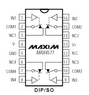
Pinout Specifications
(Voltages Referenced to GND)
V+...........................................................................-0.3V to +44.0V
V- ...........................................................................-44.0V to +0.3V
V+ to V-..................................................................-0.3V to +44.0V
COM_, IN_ (Note 1) .................................(V- - 0.3V) to (V+ + 0.3V)
NC_, NO_ (Note 2).....................................(V+ - 36V) to (V- + 36V)
NC_, NO_ to COM_ ....................................................-36V to +36V
Continuous Current into Any Terminal.................................±30mA
Peak Current into Any Terminal
(pulsed at 1ms, 10% duty cycle).........................................±50mA
Continuous Power Dissipation (TA = +70°C) (Note 2)
Plastic DIP (derate 10.53mW/°C above +70°C) ..............842mW
Narrow SO (derate 8.70mW/°C above +70°C) ................696mW
CERDIP (derate 10.00mW/°C above +70°C).....................800mW
Operating Temperature Ranges
MAX451_C_ E ..........................................................0°C to +70°C
MAX451_E_ E .......................................................-40°C to +85°C
MAX451_MJE .......................................................-55°C to +125°C
Storage Temperature Range ...............................-65°C to +150°C
Lead Temperature (soldering, 10sec) .................................+300°C
Note 1: COM_ and IN_ pins are not fault protected. Signals on COM_ or IN_ exceeding V+ or V- are clamped by internal diodes. Limit forward diode current to maximum current rating.
Note 2: NC_ and NO_ pins are fault protected. Signals on NC_ or NO_ exceeding -36V to +36V may damage the device. These limits apply with power applied to V+ or V-, or ±40V with V+ = V- = 0.
DescriptionThe MAX4511/MAX4512/MAX4513 are quad, singlepole/ single-throw (SPST), fault-protected analog switches. They are pin-compatible with the industry-standard nonprotected DG201/DG202/DG213. These new switches feature fault-protected inputs and Rail-to-Rail® signal handling capability. The normally open (NO_) and normally closed (NC_) terminals are protected from overvoltage faults up to 36V during power-up or power-down. During a fault condition, the NO_ or NC_ terminal becomes an open circuit and only nanoamperes of leakage current flow from the source, but the switch output (COM_) furnishes up to 10mA of the appropriate polarity supply voltage to the load. This ensures unambiguous rail-to-rail outputs when a fault begins and ends.
On-resistance is 175½ max and is matched between switches to 10½ max. The off-leakage current is only 0.5nA at +25°C and 10nA at +85°C.
The MAX4511 has four normally closed switches. The MAX4512 has four normally open switches. The MAX4513 has two normally closed and two normally open switches.
These CMOS switches of MAX4511 can operate with dual power supplies ranging from ±4.5V to ±18V or a single supply between +9V and +36V.
All digital inputs have +0.8V and +2.4V logic thresholds, ensuring both TTL- and CMOS-logic compatibility when using ±15V or a single +12V supply.

 MAX4511 Data Sheet


