MAX1714

Features: · Ultra-High Efficiency· No Current-Sense Resistor (Lossless ILIMIT)· Quick-PWM with 100ns Load-Step Response· 1% VOUT Accuracy Over Line and Load· 2.5V/3.3V Fixed or 1V to 5.5V Adjustable Output Range· 2V to 28V Battery Input Range· 200/300/450/600kHz Switching Frequency· Overvoltage Pr...

product image

MAX1714 Picture
SeekIC No. : 004409250 Detail

MAX1714: Features: · Ultra-High Efficiency· No Current-Sense Resistor (Lossless ILIMIT)· Quick-PWM with 100ns Load-Step Response· 1% VOUT Accuracy Over Line and Load· 2.5V/3.3V Fixed or 1V to 5.5V Adjustable...

floor Price/Ceiling Price

Part Number:
MAX1714
Supply Ability:
5000

Price Break

  • Qty
  • 1~5000
  • Unit Price
  • Negotiable
  • Processing time
  • 15 Days
Total Cost: $ 0.00

SeekIC Buyer Protection PLUS - newly updated for 2013!

  • Escrow Protection.
  • Guaranteed refunds.
  • Secure payments.
  • Learn more >>

Month Sales

268 Transactions

Rating

evaluate  (4.8 stars)

Upload time: 2024/11/27

Payment Methods

All payment methods are secure and covered by SeekIC Buyer Protection PLUS.

Notice: When you place an order, your payment is made to SeekIC and not to your seller. SeekIC only pays the seller after confirming you have received your order. We will also never share your payment details with your seller.
Product Details

Description


Features:

· Ultra-High Efficiency
· No Current-Sense Resistor (Lossless ILIMIT)
· Quick-PWM with 100ns Load-Step Response
· 1% VOUT Accuracy Over Line and Load
· 2.5V/3.3V Fixed or 1V to 5.5V Adjustable Output Range
· 2V to 28V Battery Input Range
· 200/300/450/600kHz Switching Frequency
· Overvoltage Protection (MAX1714A)
· Undervoltage Protection
· 1.7ms Digital Soft-Start
· Drives Large Synchronous-Rectifier FETs
· 2V ±1% Reference Output
· Power-Good Indicator


Application

·Notebook Computers
·CPU Core Supply
·Chipset/RAM Supply as Low as 1V
·1.8V and 2.5V I/O Supply


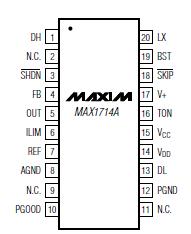
Pinout

  Connection Diagram


Specifications

V+ to AGND (Note 1)...............................................-0.3V to +30V
VDD, VCC to AGND (Note 1)......................................-0.3V to +6V
PGND to AGND (Note 1) ..................................................... ±0.3V
SHDN, PGOOD, OUT to AGND (Note 1)......................-0.3V to +6V
ILIM, FB, REF, SKIP,
TON to AGND (Notes 1, 2)...........................-0.3V to (VCC + 0.3V)
DL to PGND (Note 1)...................................-0.3V to (VDD + 0.3V)
BST to AGND (Note 1) ............................................-0.3V to +36V
DH to LX......................................................-0.3V to (BST + 0.3V)
LX to BST..................................................................-6V to +0.3V
REF Short Circuit to AGND..........................................Continuous
Continuous Power Dissipation (TA = +70°C)
16-Pin QSOP (derate 8.3mW/°C above +70°C)...............667mW
20-Pin QSOP (derate 9.1mW/°C above +70°C)..............727mW
Operating Temperature Range ..........................-40°C to +85°C
Junction Temperature......................................................+150°C
Storage Temperature Range ............................-65°C to +150°C
Lead Temperature (soldering, 10s) .................................+300°C


Description

The MAX1714 pulse-width modulation (PWM) controller provides the high efficiency, excellent transient response, and high DC output accuracy needed for stepping down high-voltage batteries to generate lowvoltage CPU core or chip-set/RAM supplies in notebook computers.

Maxim's proprietary Quick-PWM™ quick-response, constant-on-time PWM control scheme handles wide input/output voltage ratios with ease and provides 100ns "instant-on" response to load transients while maintaining a relatively constant switching frequency.

The MAX1714 achieves high efficiency at a reduced cost by eliminating the current-sense resistor found in traditional current-mode PWMs. Efficiency is further enhanced by an ability to drive very large synchronousrectifier MOSFETs.

Single-stage buck conversion allows these devices to directly step down high-voltage batteries for the highest possible efficiency. Alternatively, two-stage conversion (stepping down the +5V system supply instead of the battery) at a higher switching frequency allows the minimum possible physical size.

The MAX1714 is intended for CPU core, chipset, DRAM, or other low-voltage supplies as low as 1V. The MAX1714A is available in a 20-pin QSOP package and includes overvoltage protection. The MAX1714B is available in a 16-pin QSOP package with no overvoltage protection. For applications requiring VID compliance or DAC control of output voltage, refer to the MAX1710/MAX1711 data sheet. For a dual output version, refer to the MAX1715† data sheet.


Customers Who Bought This Item Also Bought

Margin,quality,low-cost products with low minimum orders. Secure your online payments with SeekIC Buyer Protection.
Optical Inspection Equipment
Static Control, ESD, Clean Room Products
Programmers, Development Systems
Fans, Thermal Management
Sensors, Transducers
Potentiometers, Variable Resistors
View more