MAX118

Features: ` Single +5V Supply Operation` 4 (MAX114) or 8 (MAX118) Analog Input Channels` Low Power: 40mW (operating mode) 5W (power-down mode)` Total Unadjusted Error 1LSB` Fast Conversion Time: 660ns per Channel` No External Clock Required` Internal Track/Hold`1MHz Full-Power Bandwidth` Internall...

product image

MAX118 Picture
SeekIC No. : 004408576 Detail

MAX118: Features: ` Single +5V Supply Operation` 4 (MAX114) or 8 (MAX118) Analog Input Channels` Low Power: 40mW (operating mode) 5W (power-down mode)` Total Unadjusted Error 1LSB` Fast Conversion Time: 660...

floor Price/Ceiling Price

Part Number:
MAX118
Supply Ability:
5000

Price Break

  • Qty
  • 1~5000
  • Unit Price
  • Negotiable
  • Processing time
  • 15 Days
Total Cost: $ 0.00

SeekIC Buyer Protection PLUS - newly updated for 2013!

  • Escrow Protection.
  • Guaranteed refunds.
  • Secure payments.
  • Learn more >>

Month Sales

268 Transactions

Rating

evaluate  (4.8 stars)

Upload time: 2024/11/27

Payment Methods

All payment methods are secure and covered by SeekIC Buyer Protection PLUS.

Notice: When you place an order, your payment is made to SeekIC and not to your seller. SeekIC only pays the seller after confirming you have received your order. We will also never share your payment details with your seller.
Product Details

Description


Features:

` Single +5V Supply Operation
` 4 (MAX114) or 8 (MAX118) Analog Input Channels
` Low Power: 40mW (operating mode)
                       5W (power-down mode)
` Total Unadjusted Error 1LSB
` Fast Conversion Time: 660ns per Channel
` No External Clock Required
` Internal Track/Hold
`1MHz Full-Power Bandwidth
` Internally Connected 8th Channel Monitors Reference Voltage (MAX118)


Application

·High-Speed DSP
·Remote Data Acquisition
·Portable Equipment
·Communications Systems


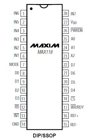
Pinout

  Connection Diagram


Specifications

VDD to GND............................................................-0.3V to +7V
Digital Input Voltage to GND ..................... -0.3V to (VDD + 0.3V)
Digital Output Voltage to GND ...................-0.3V to (VDD + 0.3V)
REF+ to GND............................................-0.3V to (VDD + 0.3V)
REF- to GND.............................................-0.3V to (VDD + 0.3V)
IN_ to GND ............................................. -0.3V to (VDD + 0.3V)
Continuous Power Dissipation (TA = +70)
    24-Pin Narrow Plastic DIP
    (derate 13.33mW/ above +70)...............................1.08W
    24-Pin SSOP (derate 8.00mW/ above +70)...........640mW
    24-Pin Narrow CERDIP
    (derate 12.50mW/ above +70)....................................1W
    28-Pin Wide Plastic DIP
    (derate 14.29mW/ above +70).............................. 1.14W
    28-Pin SSOP (derate 9.52mW/ above +70).......... 762mW
    28-Pin Wide CERDIP
    (derate 16.67mW/ above +70)..............................1.33W
Operating Temperature Ranges
    MAX114/MAX118C_ _....................................... 0 to +70
    MAX114/MAX118E_ _.................................... -40 to +85
    MAX114/MAX118M_ _ .................................-55 to +125
Storage Temperature Range .............................-65 to +150
Lead Temperature (soldering, 10sec) .............................+300


Description

The MAX114/MAX118 are microprocessor-compatible, 8-bit, 4-channel and 8-channel analog-to-digital converters (ADCs). They operate from a single +5V supply and use a half-flash technique to achieve a 660ns conversion time (1Msps). A power-down (PWRDN) pin reduces current consumption typically to 1A. The devices return from power-down mode to normal operating mode in less than 200ns, allowing large supplycurrent reductions in burst-mode applications (in burst mode, the ADC wakes up from a low-power state at specified intervals to sample the analog input signals). Both converters include a track/hold, enabling the ADC to digitize fast analog signals.

Microprocessor (P) interfaces are simplified because the ADC can appear as a memory location or I/O port without external interface logic. The data outputs use latched, three-state buffer circuitry for direct connection to an 8-bit parallel P data bus or system input port. The MAX114/MAX118 input/reference configuration enables ratiometric operation.

The 4-channel MAX114 is available in a 24-pin DIP or SSOP. The 8-channel MAX118 is available in a 28-pin DIP or SSOP. For +3V applications, refer to the MAX113/MAX117 data sheet.


Customers Who Bought This Item Also Bought

Margin,quality,low-cost products with low minimum orders. Secure your online payments with SeekIC Buyer Protection.
LED Products
Power Supplies - External/Internal (Off-Board)
Tapes, Adhesives
803
Programmers, Development Systems
Potentiometers, Variable Resistors
Boxes, Enclosures, Racks
View more